

Tzk
-
Posts
229 -
Joined
-
Last visited
-
Days Won
9
Content Type
Profiles
Forums
Events
Blogs
Posts posted by Tzk
-
-
3 minutes ago, I.nfraR.ed said:
You only need to add in _EN_CODE.BIN the starting addresses of the label heading and first option item, right?
Correct. Just give me a few minutes, i'm on the way of writing everything down

-
Ok, checked and confirmed everything is working. So here's my ISA option rom for the A7N8X. I use cmos registers 75h, 76h and 77h to store my custom settings. As all settings only got 16 values i use 4 bits of every register to store a single setting:
75h: F0h is Drive Strength, 0Fh is Slewrate
76h: F0h is Super Bypass, 0Fh is Data Scavenged Rate
77h: F0h is Auto Precharge
Everything else is in the comments of the ISA option rom. If you got questions, as always, just ask
") I used FASM to write this, so load this into FASM, hit compile and you get the option rom (4096bytes) which you can just include in your bios via cbrom.exe bios.bin /isa option-rom-file.bin. Note that this won't do anything unless you implement the bios items to actually store data in cmos register 75h to 77h.
I used FASM to write this, so load this into FASM, hit compile and you get the option rom (4096bytes) which you can just include in your bios via cbrom.exe bios.bin /isa option-rom-file.bin. Note that this won't do anything unless you implement the bios items to actually store data in cmos register 75h to 77h.
Next up i probably need to write down how i modified the bios itself...
So first i needed new labels for the available selections of the new items. To get these, i created a new label group in _EN_CODE.bin. _EN_CODE.bin works like this:
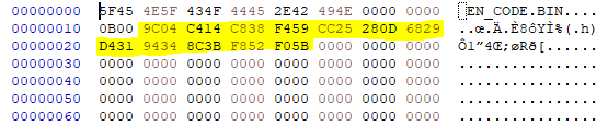
At the start of the file you got a lookup table for the different label groups which points at the label group header. Below is my _EN_CODE.bin where i marked the available groups in yellow. If you'd have a look at for example offset 049Ch, 14C4h and so on, you'd find the label group headers there. Note that the label pointers are stored in little endian, so least significant byte first. You can just add another group and the bios will recognize it. In this case you could add your label directly after F05B (offset 5BF0h). Just remember to count the label number and note it down. We'll need this later when we modify the bios item in system.bin.
Now, let's jump to the last group to see how it looks like. The last group is F05B and thus we jump to offset 5BF0h:
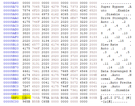
Note that the first byte is 0A which is the number of sublabels this group has. In this case we got 10 labels and thus the value stored here is 0Ah. These 10 sublabels are again pointer to the actual label text and (of course) again in little endian notation. So the first label is 705A which translates to offset 5A70h. If we have a look at this offset, we read "Super Bypass" which is the actual item label text the bios will display. Note that every label must be preceeded by 00h and if you need spaces, you must use 20h instead of 00h. That's why "Super Bypass" is followed by 2020h and then a single 00h right in front of the next label. If you add a pointer for a new sublabel, always make sure to point to the label start and not the 00h right in front of it.
Now if you want to create a group of selectable items, make sure all items got the exact same length. So if one items got a longer name, you'll need to fill all other options with spaces (use 20h for this, not 00h!) until all options got the same total length. You only need to point to the first label on the sublabel lookup table, the bios will read the following selection labels automatically. It also doesn't matter where you store the group+pointers relative to your labels. As long as the offsets are correct, it'll work.
Next up is the system.bin with the bios item strings as we need to make the bios use our newly added labels. On the PDF i linked we find this:
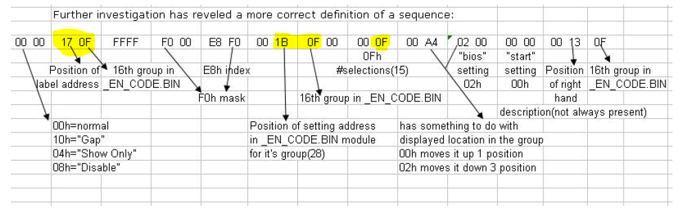
The bytes we're interested in are marked in yellow. To the left there's the pointer to the label of the option itself, in the middle there's the pointer to the available/selectable options and to the right there's the number of selectable options available.
What we need to do now is to insert the position of our group in _EN_CODE.bin (1st, 2nd, 3rd group etc) into the bios item string and the position of our label inside that group. So inserting 05 06 would read the 5th label from the 6th label group. This applies for the item itself and also the selections. We also need to tell the bios how many options are available, else it won't read all labels correctly.
Note: I'm not sure if the bios started counting at zero or 1. Iirc the 2nd group gets 01 as pointer. So better doublecheck this with a known to be working option on the bios.
If everything went smoothly, we now got an option in bios which has the correct name and selections available. If you want to test this fast, just add system.bin and _EN_CODE.bin to a bios file with cbrom and open it with modbin. If modbin displays the menu tree correctly, there's a good chance at the bios will work. No other modules are needed inside the bios for this first test.
What now needs to be done is to tell the bios which Cmos register it should write to. This is done by changing the "E8h" index shown above. That's the cmos register the bios will write to. Make sure you don't choose a register which is already in use! I used r/w everything (windows tool) on the stock bios to see the content of all Cmos registers before choosing 75h to 77h on my mod. The masks mentioned next to it allows to for example only write the first or last 4bits of the register. So if you want to store two settings on a single register, choose masks 0Fh on the first and masks F0h on the 2nd bios item. The selections will write the register content in increasing order. So if your selection labels are named linke this:
- Auto
- Ten
- twenty
- hundred
Then Auto will write a zero, ten will write a 1, twenty a 2 and hundred a 3 to the cmos register. I always chose Auto as first item, so i can just check if the register is 0 in my option rom. And if yes, i just skip the custom code.
-
 1
1
-
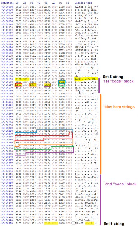
I investigated the bios item strings in system.bin further and i noticed something. Before and after each bunch of strings, there's some "code". The code before each bunch seems to indicate where the strings start. On Asus the system.bin includes the bios items starting at 10000h, so i assumed that the code doesn't assume this offset. So i copied everything to a new file (10000h offset now gone) and tried my luck.
Note that each bunch of bios items seems to start with 246D 6C24h which translates to $ml$ (marked in yellow). I then noticed that the immediately following codeblock seems to have increasing numbers following each other. And it looks like that these numbers actually indicate where the bios items are saved. For example the blue box at offset 1ACh has B602h in it which is an address written in little endian (least significant byte first). So we swap bytes: B602h -> 02B6h. And guess what, the corresponding bios item string starts at 02B6h (big blue box at the bottom). This is the same for the other boxes i marked.
I don't know what the numbers inbetween the small boxes do, but they seem to point to the codeblock following after the bios items. So i assume this is a lookup table for the bios items and some other setting.
My current conclusion is:
I tried adding new bios items before and that bricked the bios file. I assume that it broke because i tried to add new items at the start (near initial offset 10000h). This would cause all following $ml$ blocks to have an offset, as i had to insert a few bytes. Now, that'd break all following lookup tables and i'd miss the new item on the corresponding lookup table.
So it looks like we'd need to: 1. insert a new item, 2. add it to the lookup table 3. add the following setting pointing to the end of the segment and 4. correct any offset we broke by inserting some bytes.
But first, we need to figure out what the 2nd codeblock directly after the item strings does.
-
Well, i'm still looking for SuperBypass... Everything else works and i need to test it with Winbond Sticks. But before trying this, i'll document how i did it and upload the source of my ISA option rom somewhere. So you guys can either do this mod yourself or at least i know in a few months how i did it.
It shouldn't be too difficult to port this to other Asus boards, at least when they also got 5 unused settings in bios.
-
So... I just finished setting everything inside my option rom up. BUT i think that the SuperBypass register is wrong. Tictac mentioned it at B0D0F4 register 91h. He also mentioned AutoPrecharge and DataScavengedRate at B0D0F4 which both actually are at B0D0F1. Oops... I located the latter two, but can't find SuperBypass...
Next up is checking if AutoPrecharge, DataScavRate, Slew and DriveStrength work.
EDIT: Everything works. Nice.
-
2
-
-
I'd guess that this setup menu in AWDBedit is the ITEM.BIN on later Award bios. This basically splits the bios items and the system.bin in separate files. Just open a later bios (eg athlon 64 or intel socket 775) with cbrom and check if it includes item.bin...
I just tested a few DS settings and it seems 33h is the best settings for Infineon BT-5 (found on Corsair 3200C2). I had thousands of errors when using below 22 or above 88. Probably slew rate needs also adjustments to get the maximum out of these settings.
-
I chose the following settings for now: Drive Strength, Slew Rate, SuperBypass, Data Scavenged Rate and Auto Precharge. I'm not sure i need the last (AP), but it should be possible to for example set Dimms 1&2 with one setting and Dimm 3 with another setting. You mostly wouldn't run 3 Dimms anyways. Or you could set the first set of registers differently than the others (like Asus did). Or we could add a completely different setting.
I'd love to add all alphatimings, however i'd need to find a way to add extra settings to the bios. The PDF described how you'd do it on a newer bios with ITEM.BIN module, but sadly not for ITEM.BIN-less bios. Just adding a setting to system.bin bricked the bios when i tested this. My assumption is that the code blocks before and after the actual settings are used for the settings itself and thus you can't just add a new setting in the middle.
-
Doublepost to keep things separated.
Next up i booted the board with stock settings at different FSBs to check default drive strength. Note that Asus seems to set the registers in pairs. We got 6 registers (2 for each Dimm), and Asus sets it like: Dimm1: A B, Dimm2: A B, Dimm 3 A B with A and B being different drive strengths. Results:
- 133 FSB: 55 99
- 166 FSB: 33 99
- 200 FSB: 33 44
- 200+: 33 44 (no change after that)
So now i'm unsure how the options are mapped in bios. On DFI Ultra-D (NF4) the even values were "strong" and the uneven values were "weak". This resulted in a table like this:
(weakest) 7 5 3 1 2 4 6 8 (strongest)
I'm unsure if this is also the case on Socket A. However i'd assume that Asus might increase the strength with higher FSBs. As they go from 55 to 33 and from 99 to 44 it might be the same as on NF4. Maybe someone of you guys knows this...?
-
I tried to add more settings but still didn't succeed. I haven't tried another time though. So currently i'm working with the unused 5 items i got. It must be possible to add more items as DFI uses 260+ and Asus uses 210+, but i coulnd'd figure out how up to now.
Currently i added custom settings like this:
- Search the bios for the 5 unused items and rename them
- Add a new label group and subitems (selectable choices) in _EN_CODE.BIN
- Make the 5 items point to the subitems in EN_CODE.bin and configure it for the correct amount of choices
- Configure the mask and (custom) cmos register for the 5 new items, this will write to the desired register when selecting an option in bios
Now we got 5 new items which already have selctable choices in bios and store their settings correctly inside cmos registers. What's missing is code to actually do something. So next up we do this:
- write an ISA option rom which reads the Cmos register we configured in 4)
- based on the register value we do nothing (when setting is set to "auto") or set the desired value
That's it. I configured the settings to default to "auto" which will write a zero to the cmos register. This will just jump my custom code and do nothing. For the drive strength i currently use a single setting and register to set 00 to FF (which is 0Fh different choices) and just write all 6 available registers with the same value. I'm not sure we need to be able to set all strengths differently.
I use FASMW to compile assembler to usable binary.
Now, you asked how i read the Cmos register values. Here's my heavily commented code which is based on TicTacs A64 patcher code:
;read drive strength
;this is where the drive strength AND slew rate setting is stored
;i chose the first 4 bits for drive strength and the last 4 bits for slewrate
;so register 75h = 0Fh is drivestrength auto, slew rate 15
;and register 75h = F0h is drivestrength 15 and slewrate auto


mov al, 75h     ;index - 75h, set cmos register index address
out 072h, al    ;send register offset to special address register
in al, 073h     ;fetch data from special data register
and al, 0F0h    ;mask al to discard last 4 bits as these are used for slew rate
cmp al, 00h     ;check if Drive Strength is set to auto and if yes
je slewrate     ;jump to next setting(equal 0000.0000)

cmp al, 10h         ;check if DS is set to 1
je drivestrength1   ;jump if equal 0001.0000

(....)              ; we check up to 15 as this is the highest possible setting

cmp al, F0h         ;check if DS is set to 15
je drivestrengthF   ;jump if equal 1111.0000
And here's the code i currently use to set the drive strength registers. Note that i'm intentionally not using macros to keep it simple and i'd call this some sort of spaghetti code
")
;set drivestrength = 11h drivestrength1: mov eax,080000464h ; 1st drive strength address for offset 65 and 67 mov ebx,011001100h ; 1st data for 1st address, offset 65 and 67 mov dx,0CF8h ; out dx,eax ; mov dx,0CFCh ; in eax,dx ; and eax,000FF00FFh ; mask data. removes the old data from eax or eax,ebx ; out dx,eax ; ; mov eax,080000470h ; 2nd drive strength address for offset 71 and 73 mov ebx,011001100h ; 2nd data for 2nd address, offset 71 and 73 mov dx,0CF8h ; out dx,eax ; mov dx,0CFCh ; in eax,dx ; and eax,000FF00FFh ; mask data. removes the old data from eax or eax,ebx ; out dx,eax ; ; mov eax,08000047Ch ; 3rd drive strength address for offset 7D mov ebx,000001100h ; 3rd data for 3rd address, offset 7D mov dx,0CF8h ; out dx,eax ; mov dx,0CFCh ; in eax,dx ; and eax,0FFFF00FFh ; mask data. removes the old data from eax or eax,ebx ; out dx,eax ; ; mov eax,080000480h ; 4th drive strength address for offset 81 mov ebx,000001100h ; 4th data for 3rd address, offset 81 mov dx,0CF8h ; out dx,eax ; mov dx,0CFCh ; in eax,dx ; and eax,0FFFF00FFh ; mask data. removes the old data from eax or eax,ebx ; out dx,eax ; ; jmp slewrate ; jump to next setting -
Afaik every version of AWDBedit corrupts the bios when you save it, at least for Award v6.0PG. Might work for 4.51, though.
When i got everything working on my modbios, i'll upload the code somewhere and write down how i did it. Implementing new items is easier than one might think
-
 1
1
-
-
Success!
I'm able to change my custom settings in bios, this is then saved to CMOS registers by the bios. Then during boot my custom ISA option rom reads the CMOS registers and sets the corresponding values based on the cmos register.
I still got a off-by-one error i must trace down, but in theory it works. I'm currently setting registers 64, 66, 70, 72, 7E (last register is missing) while i want to set 65, 67, 71, 73, 7D and 81.
-
1
-
-
I updated the DFI LPB Merlin bios. Thorn noticed that i accidentally used the wrong system module (discovery 0.1 instead of 0.3) for the romsip swap. So here's the updated version, this time with a) correct system.bin module and b) changed post message to indicate the romsips. No other changes were made and the bios is untested.
MerlinDiscovery0.3+ebed+ed.zip
You can also find the archive here: http://bierbude.spdns.org:2302/USER UPLOADS/Tzk/DFI/Lanparty Ultra B/
-
1
-
-
Your PCR works as expected. Thanks!
I doublechecked with NF2 Tweaker and this works:
Auto Precharge
offset 0x86h
0Fh = 00001101b = enabled
0Dh = 00001111b = disabled
And i found+checked these:
			****************************
				* nVidia nForce2 Data Base *
				****************************

1) AGP  Controller Latency
  *************************
	PCI Bus#0 Dev#30 Func#0 Offset#0D

		      0D
	- 16  clock : 10
	- 32  clock : 20
	- 64  clock : 40
	- 96  clock : 60
	- 128 clock : 80
	- 160 clock : A0
	- 192 clock : C0
	- 224 clock : E0
	- 255 clock : FF


2) AGP  Bus Latency
  ******************
	PCI Bus#0 Dev#30 Func#0 Offset#1B

		      1B
	- 16  clock : 10
	- 32  clock : 20
	- 64  clock : 40
	- 96  clock : 60
	- 128 clock : 80
	- 160 clock : A0
	- 192 clock : C0
	- 224 clock : E0
	- 255 clock : FF


3) PCI Latency
  *************
	PCI Bus#0 Dev#8 Func#0 Offset#1B

		      1B
	- 16  clock : 10
	- 32  clock : 20
	- 64  clock : 40
	- 96  clock : 60
	- 128 clock : 80
	- 160 clock : A0
	- 192 clock : C0
	- 224 clock : E0
	- 255 clock : FF


4) CPU Disconnect Function
  *************************
	PCI Bus#0 Dev#0 Func#0 Offset#6C,6D,6E,6F

		    6C 6D 6E 6F
	- Enable  : 01 FF 01 1F/9F
	- Disable : 01 FF 01 8F


5) Command Per Clock (T1/T2)
  *******************
  	PCI Bus#0 Dev#0 Func#1 Offset#84,85,86,87

		    84 85 86 87
	- Enable  : F3 13 0F 03
	- Disable : F3 13 0F 23

	WARNING! (Not Editable after boot, Can only be set before memory sizing)


6) Alpha Memory Setting
  **********************
	PCI Bus#0 Dev#0 Func#1 Offset#94,95,96,97

		    94 95 96 97
	- T(DOE)  :	     x	Selectable Value: 0,1,2,3,4,5,6
	- T(RRD)  :           x Selectable Value: 0,1,2,3,4,5,6
	- T(W2P)  :       x	Selectable Value: 0,1,2,3,4,5,6
	- T(W2R)  :        x	Selectable Value: 0,1,2,3,4,5,6
	- T(REXT) :    x	Selectable Value: 0,1,2,3
	- T(R2P)  :     x	Selectable Value: 0,1,2,3,4,5,6
	- T(R2W)  : x 		Selectable Value: 0,1,2,3,4,5,6
	- reserved:  -		Selectable Value: -

	- Offset 94 = XY
		X= T(R2W)	Selectable Value: 0,1,2,3,4,5,6
		Y= Reserved	-

	- Offset 95 = XY
		X= T(REXT)	Selectable Value: 0,1,2,3,
		Y= T(R2P)	Selectable Value: 0,1,2,3,4,5,6

	- Offset 96 = XY
		X= T(W2P)	Selectable Value: 0,1,2,3,4,5,6
		Y= T(W2R)	Selectable Value: 0,1,2,3,4,5,6

	- Offset 97 = XY
		X= T(DOE)	Selectable Value: 0,1,2,3,4,5,6
		Y= T(RRD)	Selectable Value: 0,1,2,3,4,5,6


7) Side Band Addressing
  **********************
	PCI Bus#0 Dev#0 Func#0 Offset#49

		    49
	- Enable  : 03
	- Disable : 01
Source: http://forums.pcper.com/showthread.php?335978-DFI-Alpha-setting-come-in
-
Maybe the setting you've found is some kind of drive strength? Can't be a timing or else it'd probably influence bandwidth. I'm curious what it is
PCR sounds great, should make our life easier.
Next i'll try to add the black.bin ISA rom from TicTacs bios to see if it crashes my a7n8x and if it sets the disconnect feature correctly.
-
Yep, 3EG Rev3 seems to be based on 1/21. Interestingly Merlin ED and Hellfire 3EG Rev3 is nearly identical... Only a few values are different which improve system stability with multi 10 to 12.5.
EDIT: 3EG Rev3 is identical with Merlin DFI 12/31. So i assume that Hellfire based his bios on DFI 12/31. There's only a tiny difference between DFI 1/21 and 12/31.
I've yet to extract all romsips from DFI official and beta bioses though.
-
At least from my side it's fairly simple: First, i only got Abit and Asus boards and second Hellfire seems to miss a changelog, so no clue what he did on the modbios he released... On LP B he used the 6/19 bios (and possibly also 6/19 romsips). That's what Trats ported to A7N8X in his 1008mod3 bios. I tried it and couldn't make it past 245Mhz 24/7 stable. With Merlin EBED (which is somewhat based on DFI 1/21 romsips) i'm able to reach >255MHz.
So in simple terms: i didn't see any need to investigate the hellfire bioses
I grew up clocking NF2 boards and was always limited by my knowledge. That's why i started pushing further as this is what socket A deserves ❤️
-
I just tried combining the romsips to see if there is any effect, especially since i knew that Trats and Mantarays is clocking worse than Taipan on my asus... And i found that the limit indeed is lower on both. Haven't had a look at your tables up to now.
If you need further data for the registers i can dump via wpcredit on my a7n8x dlx and a7n8x-x. Just tell me which registers you need. If you could make the newer settings work in Zenstates app that'd be awesome. I've had a brief look for A64 Tweaker and NF2 Tweaker sources, but it seems like CodeRed never released those to the public.
I haven't had time to actually test a custom ISA rom, but that's my next goal: to get an ISA rom for DriveStrength, Slewrate, SuperBypass and DataScavengeRate working and on top of that read Cmos registers and set these settings depending on the cmos register content. That way i should get fully working bios options for those. The b-d-f registers itself should mostly consist of 4bit settings. So either the upper or lower half of the bytes are used for a single setting (except settings like Tras with >8 choices). Afaik the right half of settings on NF2 Tweaker are all 4bits. Tras, Trc, Trfc and the AGP/PCI latency should be 8bits. DriveStrength and Slewrate too. Not sure about SuperBypass and DataScavengedRate, but i'd guess 4bits.
Again some code i found for option roms: https://gist.github.com/DruckiMcDruck/10d22bef2ac6ed1673ff15210c8aefb8
And here's a list with registers i found on different forums so far: https://gist.github.com/DruckiMcDruck/01174f3cd2bc2c1df6a7aa366060f304
-
If Tref setting is available on NF2, then it is unknown. As we can control Alphatimings, i'd try to get Slewrate, Drive strength, SuperBypass and DataScavenged Rate working. Sadly NF2 Tweaker source isn't available and thus we have to manually find the registers. Afaik DFI has them in bios, so this might be a way to find them.
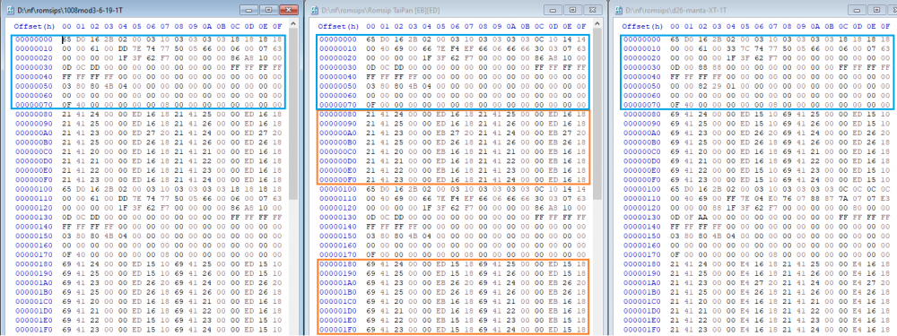
Here's what i used for my comparison of romsips. I combined the blue first half with the orange 2nd half. Left is trats, middle is EBED and right is mantarays XT.
Next up i'll swap the A7N8X and try my NF7. Maybe i can get it into a working state. And i'd like to try Merlins Bios, as up to now i mostly ran Mantarays XT.
-
I did a quick comparison between my modded romsips. Base is Taipan EBED romsips + 3.19 BPL, CPC on. I then swapped the first half of the romsips to Trats 1008mod3 and D26 Mantarays XT while keeping the 2nd half of EBED. Setup is A7N8X Dlx, random Tbred B, 1x512mb TCCD (Geil Ultra-X) 3-4-4-8 and Memtest v5.01. I tested Test #7, as this seems to be the indicator if the chipset is stable or not. Vdd was 1.85V, Vdimm 2.7V. Results:
EBED: 255Mhz pass, 260Mhz fail
Trats: 250 pass, 255 fail
MantaXT: 245 pass, 250 fail
So it looks like the upper half alone gives me a 10Mhz increase in stable fsb when going from MantaXT to EBED. I'll post the exact romsips i used later.
-
Well, we know all Timings in NF2 Tweaker if we a/b test them one after the other. Iirc most NF2 Tweaker Alphatimings are 4bits while for example Tras is 8bits. And if someone brave tests all available bios options on Abit and/or DFI we probably get most of them.
This might also be of great help (ISA option rom sourcecode):
http://www.xtremesystems.org/forums/showthread.php?109834-AMD-Athlon-64-DDR-ROM-Patcher
Yes, you basically want to reverse the Soft-L12 mod. Most modbios have the 200Mhz tables copied to 133 and 166Mhz, so every cpu can reach high fsb. This makes sense for unlocked cpus but will make the performance on superlocked cpus suffer. If you got enough time you could even tweak a bios for like every 10Mhz of FSB (one for ~200Mhz, 210Mhz,...) to get maximum bandwith/efficiency for low-fsb cpus. Especially superlocked Cpus with high multi and low stock fsb might profit from this.
Interesting observation that the top half of the table seems to allow for more/less fsb. I thought it's mainly the lower half which helps fsb. I built 3 romsip versions yesterday and might try max. FSB on them. I made D26 Mantarays XT upper half + EBED lower table; full EBED table and trats 1008mod3 upper + EBED lower half. Might be interesting to see how the max. fsb behaves on all of them, especially since my northbridge is definitely limiting my max. FSB. I need to increase Vdd to >1.8V to reach 255Mhz+, else i get errors in Memtest Test 7. I can't even get 2x512mb TCCD stable above 250MHz while 2x256mb Winbond is perfectly stable at 260MHz+.
-
Well, for Slewrate, Drive Strength, SuperBypass and a few other registers we do know this, right?
What i'm currently missing is the link between the bus-device-function adressing scheme and an adress like 08000C28Ch. Am i correct that this is a pci address in the pci address space? So converting this adress to binary leads to 32bits and those 32bits can be mapped to b-d-f adressing?
Example:
08000C28Ch is 10000000000000001100001010001100 in binary. Let's split this into parts as described here: https://wiki.osdev.org/PCI#Configuration_Space_Access_Mechanism_.231
result: 1 0000000 00000000 1100 0010 10001100
this translates to:
- enable bit is set
- bus is 000 -> 00h
- device is 1100 -> 0Ch
- function is 0010 -> 02h
- register is 10001100 -> 8Ch
As the address was 08000 C 2 8C h this result isn't unexpected, i guess.
Or are you trying to inject code at an earlier stage of the boot procedure? So like manipulating Dram settings while the bios load the initial values?
-
Ah well. I refused to use the newer modbin 2.04.03 because i disliked the new design. You can't see selections on the item tree anymore... That's why i stuck to 2.01.02.
I also try to stay away from disassembling the system bios as it seems to be a mess of legacy (spaghetti) code plus some legacy limitations due to x86 architecture and several relocations of code during boot + decompression trickery. It's a mess... There's the source of an older award 4.51 bios somewhere on the internet, but we're on 6.0. So the general bios layout and structure will be similar but details will differ. Pinzakkos site is a great source for the bios structure though.
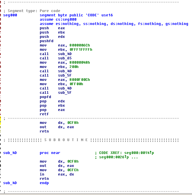
EDIT:
Here's what black.bin from blackmantarays does. It basically loads different registers and uses the different subroutines to push data through the PCI address- and dataport. All used subroutines look similar, but with variing ports. This looks like the examples shown on the PDF i linked, but uses subroutines to reduce code duplication.
-
1
-
-
I just built some custom romsips with the upper half of D26 Mantarays XT, Taipan EBED and Trats 1008mod3 while keeping the lower half of Taipan EBED. B0D0F0, F2, F3 and F4 differ while B0D0F1 and F5 stay the same. However on B0D0F4 the only difference i get is A4h and A5h, everything else is identical. So no different Slewrate or DriveStrength.
Aren't these repeating values below the romsip just some padding bytes or placeholders? Regarding the other tables: DFI got 10 tables while all other boards got 6. Maybe the tables inside the decompression block are used as defaults during boot or when cmos defaults are loaded?
I know about the modbin method, but on winxp i can't overwrite the original.bin while modbin is open. You keep modbin open and modify original.bin while modbin is still running in the background?
I'll have a look at the Blackmantarays bios, thanks for pointing that out!
EDIT: Looks like the black.bin patches some pci registers as it writes to 0xcf8. TicTac might use this for the Cpu Disconnect Patch which is mentionen in the readme. If i got it right he writes to Cmos register 0C, 48 and 6C. Still might be a good idea to just modify this for my custom code.
-
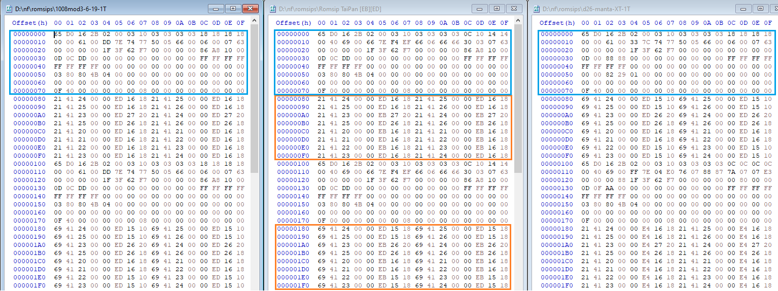
I already made a table to compare these side by side but didn't draw any conclusions. I thought that these might store subtimings/alphatimings, drive strength or slewrate. However i didn't build different romsip combinations to test this. If you want to test this, you could swap only the upper half and check registers with wpcredit to see if for example the drive strength changed.
Here's what Trats 1008mod3, Merlin ED and D26 MantaXT looks like. I marked the difference in yellow. Note that using the lower table gives me a lot of extra FSB on the Merlin bios vs. Trats (260 vs. 245Mhz). So the magic must happen in the upper half of the romsip table at offset 100h to 180h. I didn't use a multi for testing which is affected by the 1510 vs. 1518 setting (multi 10 to 12.5 i guess).
Now i should probably use a single lower half table and combine it with the different upper half tables... And then dump chipset registers with WPCRedit i guess...


A7N8X-E Deluxe as an alternative for socket 462
in Mainboards
Posted
Just edited the post above to include the addition of labels in _EN_CODE.bin...
Yes, you could probably just somehow modify it to just change the data based on the input value instead of using this (huge) switch. It's the first time i've written assembler, so i'm more or less happy that it works. It was an even bigger mess before i added the macro...