

nachtfalke
-
Posts
860 -
Joined
-
Days Won
8
Content Type
Profiles
Forums
Events
Blogs
Posts posted by nachtfalke
-
-
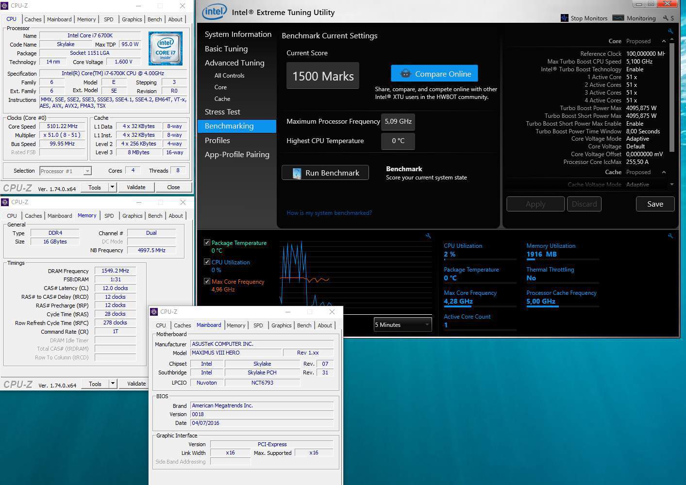
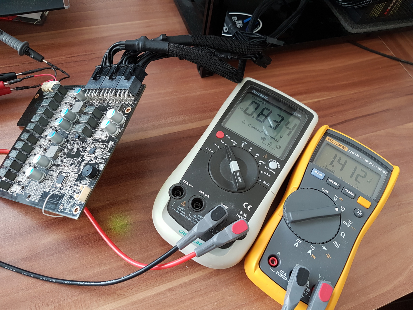
thanks , backup is at 1400
 , had in load at 1.65vgpu -106 , i measure directly from evap base with internal hole , the be accuraty , so chip was at -95 internal temp , so only 11-15 degree deltaT
 -
all informations are in those threads , when i have time i will make some pics:D
-
-
bench on chiller like a boss!
-
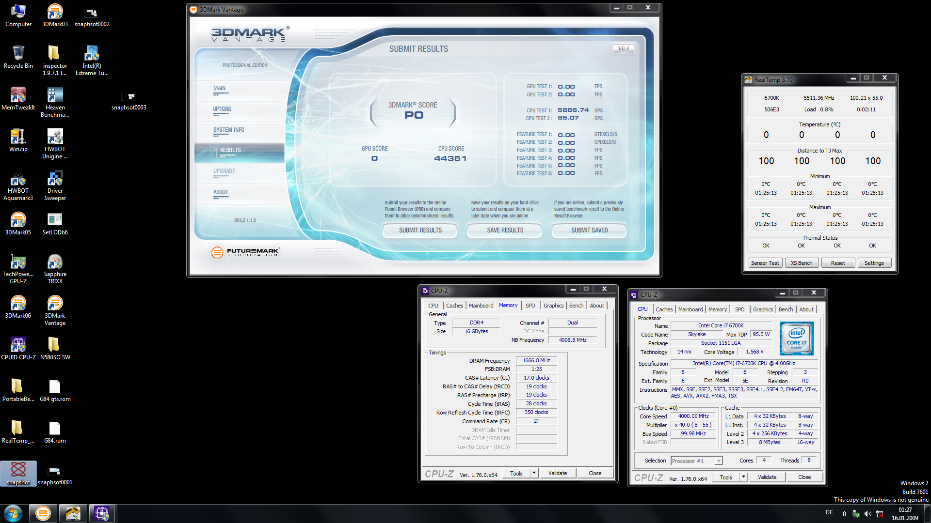
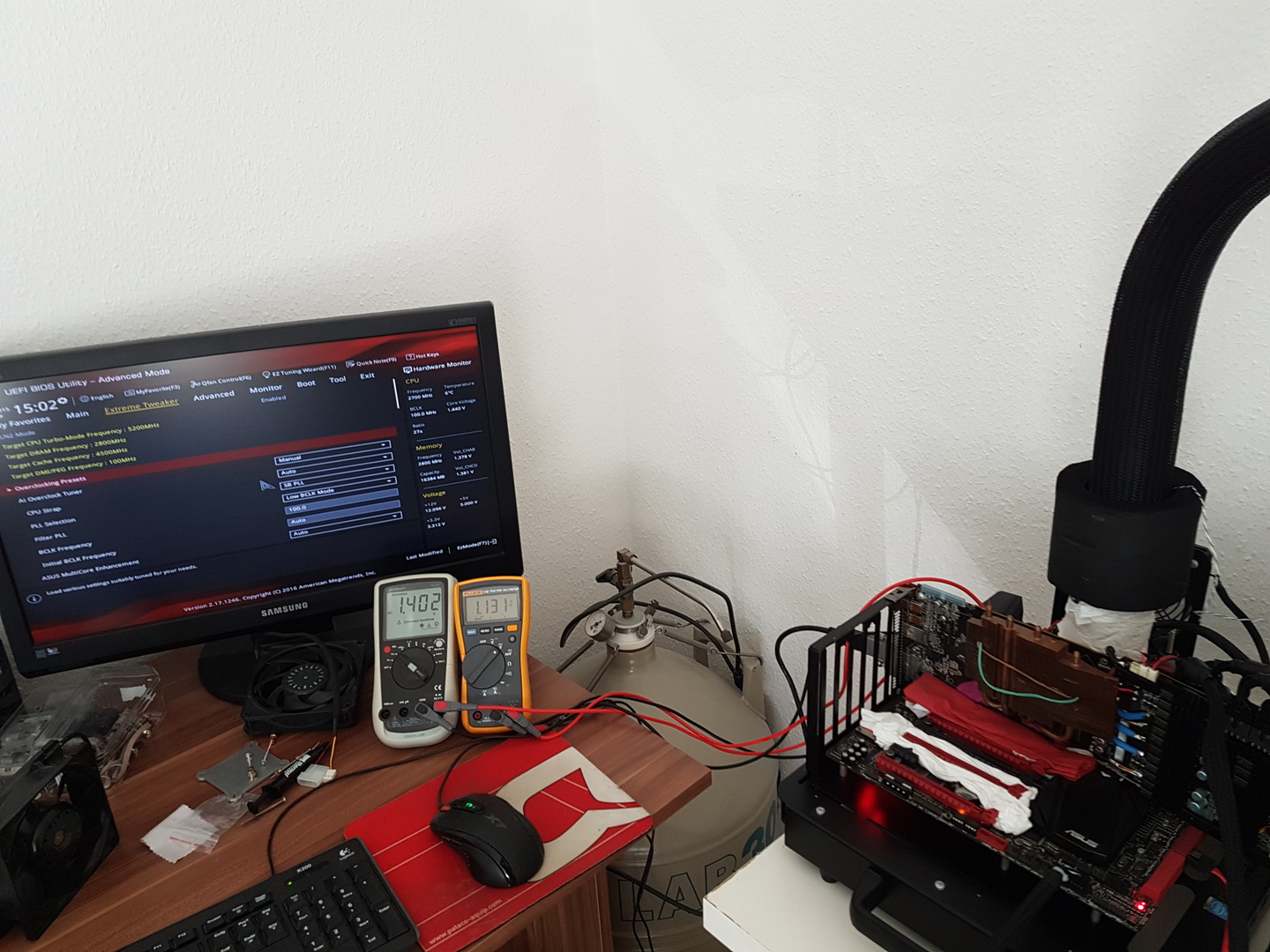
thanks! actually i was able to bench 1380mhz core clock at 1.7v , but i had issue making screenshot , on this cooling setup it can be done 32k score!
-
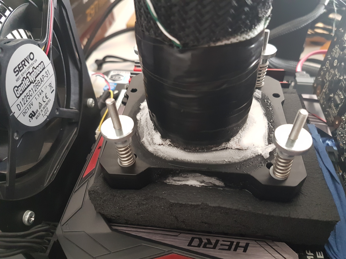
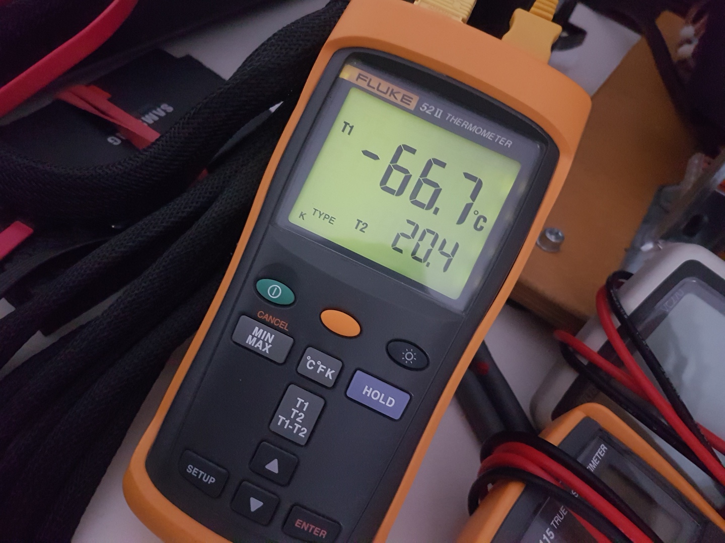
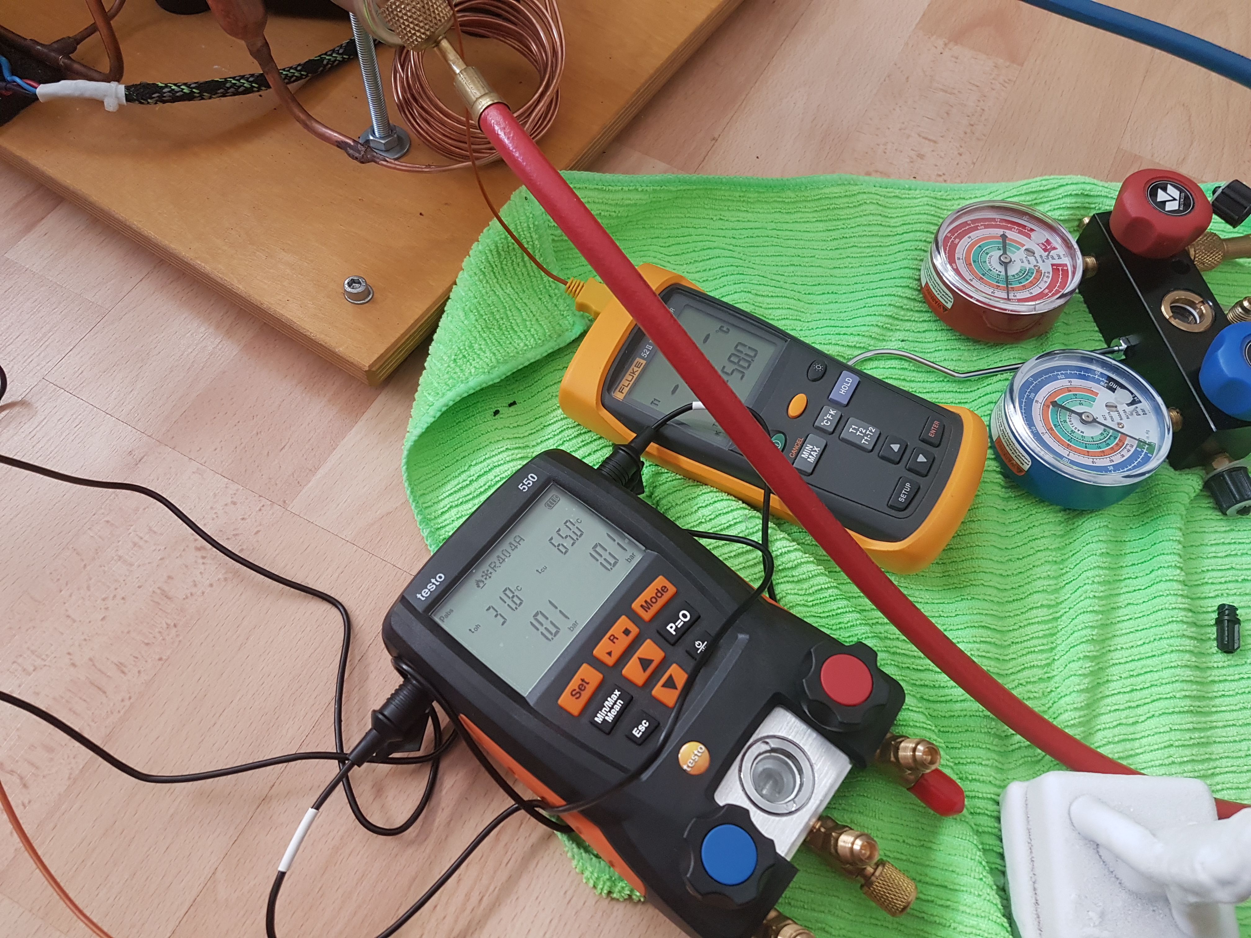
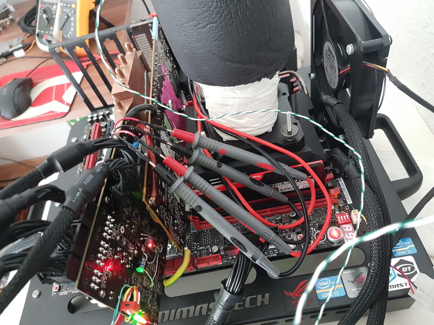
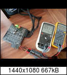
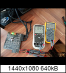
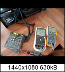
So what, if anything can be done to improve a unit such as mine ? Could I have the refrigerant removed and add a new evap head or entire line, it seems like I already have a fairly decent compressor, condensor, fan etc. I also do use an extra temp probe to get a better sence of cpu temp like in the pic below. I have also done a lot of experimenting and testing myself to maximize performance and have had decent results shaving of 30-35C

i don´t know exacly but Ron´s unit use 18ccm displacement compressor , they are ok and silent but only for a quad core , if you want to bench octocore or 10 core cpu you should switch for an rotaryes with min requires 24 -28ccm displacement!
and yes new evaporators will be required here to lowering DeltaT .also if you change that evaporator with a better one , that will change the hole unit behavior , because ratio pressure will be changed aswell , you will charge the unit with more heat from heat sources , that mean metering device ( expansion valve) will not fit at lenght anymore ...so sould be shorted again till your subcooling and superheat meat the right values with pressures!
refrigerant should be recover not removed!!!
regards!
-
What do you mean "use no regular stepper or spiral evaporator" ? I have an SS built by runmc (Ron from Under-the-Ice.com) and it uses chilly1 evap I believe and to stay subzero benching XTU (6700k 4/8) I must keep vcore under 1.5v or so. Heres pics of SS]
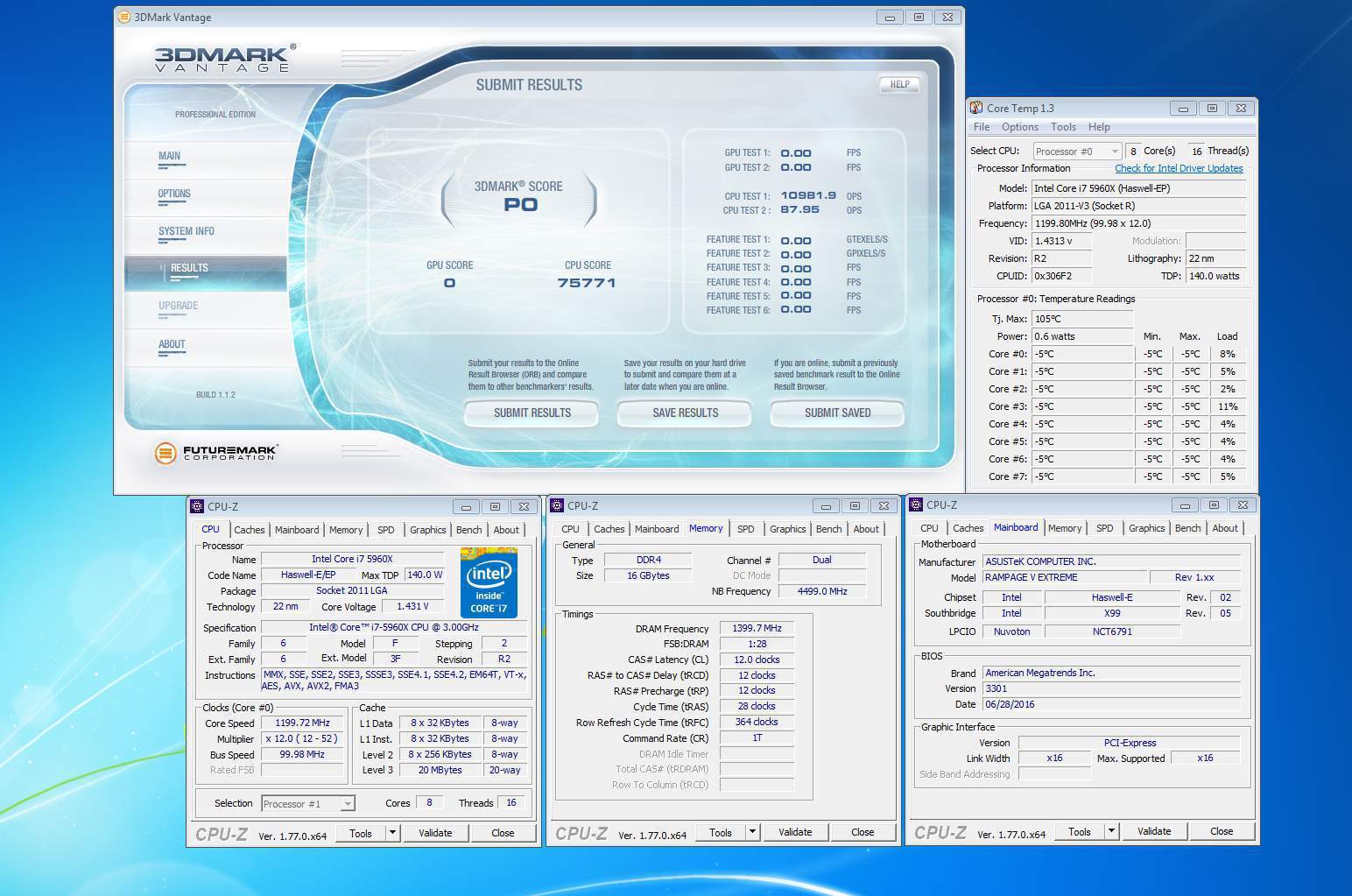
really i don´t want to start a war , but 95% of the units actually build and saled by most well know phase builder that for 99% of them are only a bussines are really ineficient units , push the phase era into inefficient unit because they want only show you just really "cold" numbers on the thermometer ...but for an overclocker not that is intrested ...intrested is how will perform delta T? so speaking about unit of above he has 78+C delta T , bench a small chip power hungry that can reach prehaps 200W at 1.65v , so benching one that can generate 400w + how will perform that unit? using a big displacement compressor will be for nothing , because the issue are the evaporators!!!!!
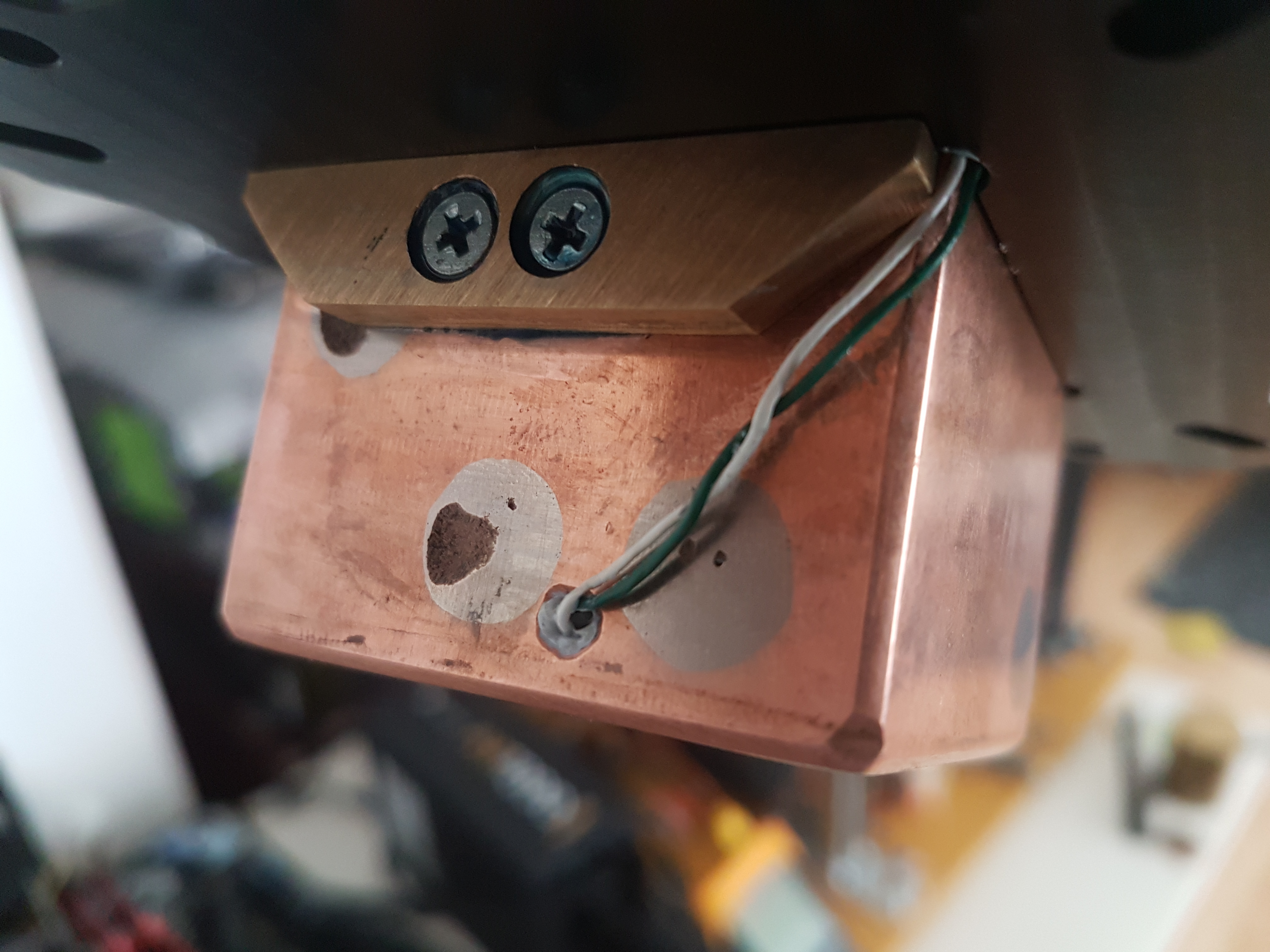
i can´t giv my all secrets here , because i get me lot of time and resurces to develop a new phase change evaporator , i can only say a phase evaporator work like a waterblock , how is build an waterblock? verticaly?? like stepper or spiral evaporator? NO NO they are flat ,because the heat is flat? ofcourse , because the copper mass will not count? ofcourse , but way? because you use an internal constant flow, in fact evaporator are closed hermeticly , the top of evaporator are NOT intrested ....only the BASE...the BASE are secret of all evaporator build ....but unfortuly stepper and spiral has only small base surface area with the heat , uso to thick copper base ( minim posible to be not bent by pressure is 4mm base thicknes), no internal arhitecture( arhitecture should be full of holes , elicoidal waves and shapes and channels- that the refigerant to enter to make better heat treansfer) on the base to incerese the heat transfer and lowering the DELTA T ...so that is main issue of these inefficient evaporators .
in fact usig spiral or stepper you overhearting the cpu or gpu under the evap base , but you are still at -40-50 in the thermometer because you only measures suction vapour temp outlet evap! so the heat reamin in the heat sources , overheating /degrading the well payed cpu and the unit are not charged with that heat , that in fact is build to disipated and cooling that heat!...but nobody say nothing!
a good waterchiller will be very close to an SS , because even they bench most on + degree ...they has maximal 20 degree delta ...not 80-100 like most SS here used:D
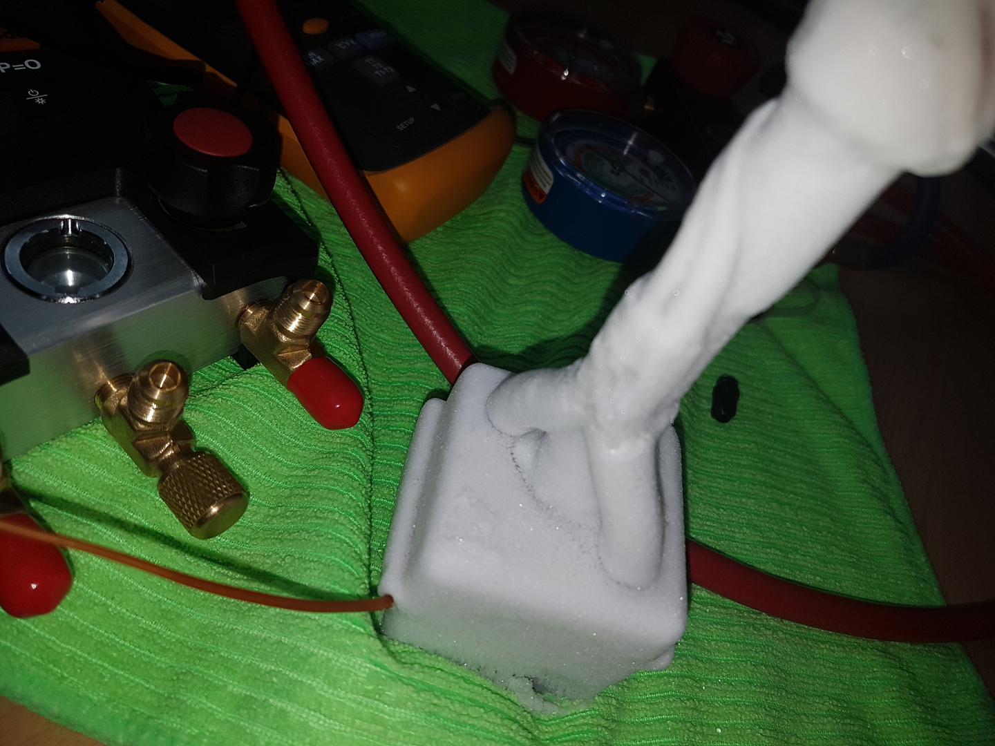
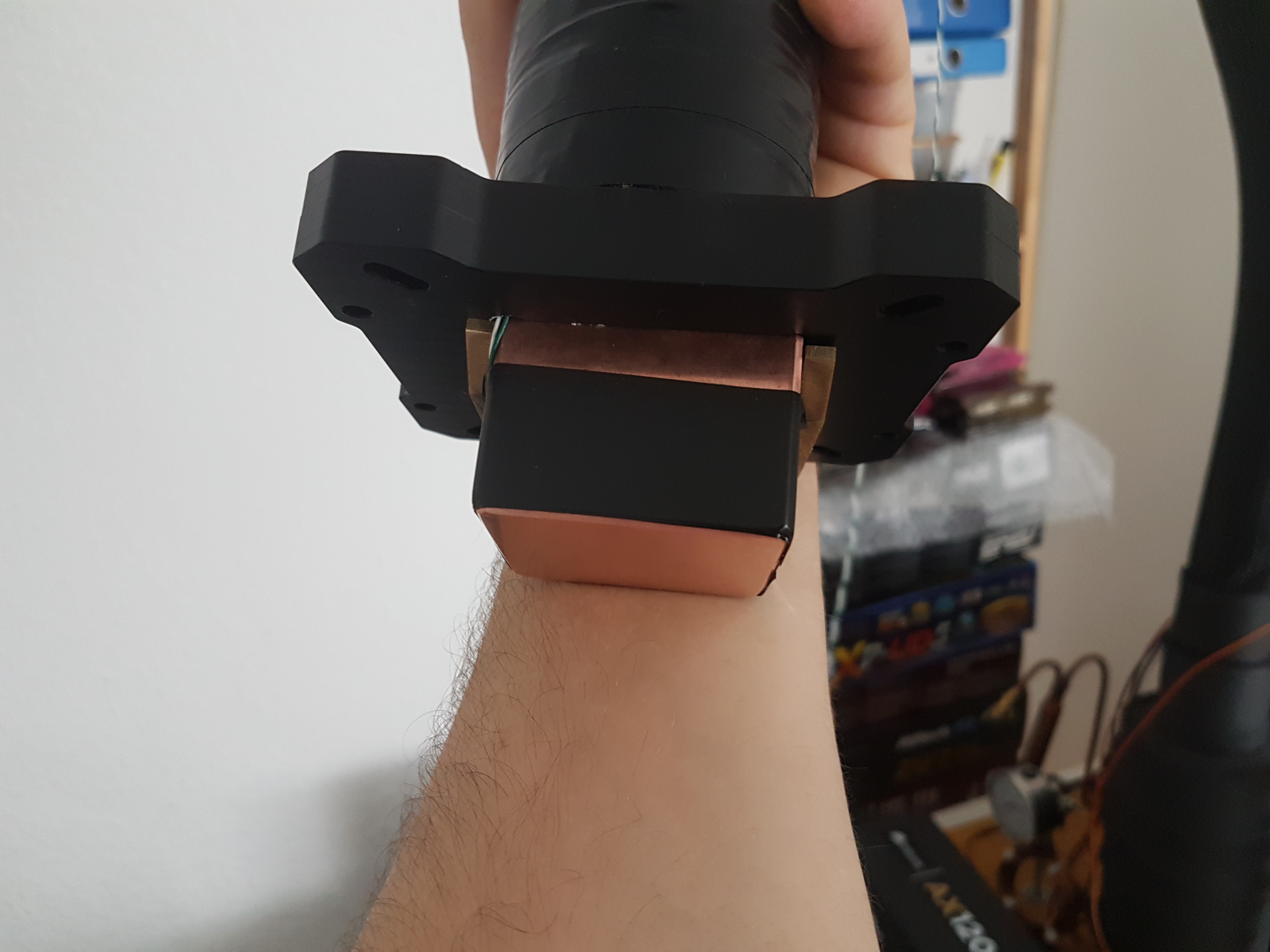
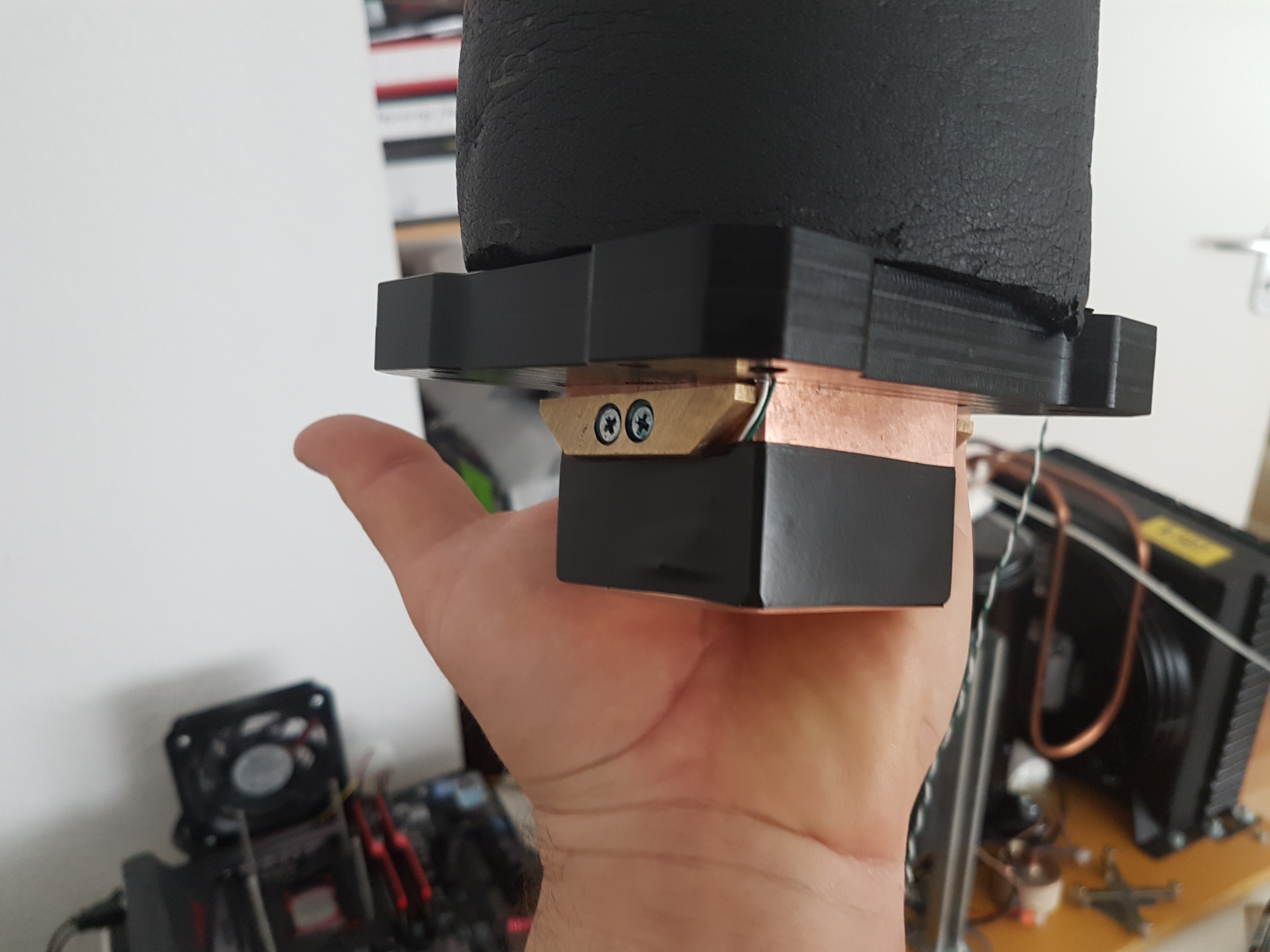
i made some test with my new evap design .
-
you are sure??? my single stage can do that , but use no regular stepper or spiral evaporator , they are inefficient regarding Delta T.
-
20 degree on big single stage?
-
You are a master!!
I removed all 3.3v lines and it powered up perfectly! I found out that 3.3v on PSI makes the phase lights show up but VTT and EN are completely not needed. The FB vmod even works, I cant thank you enough!!
i´m glad that you finnaly make it working
i posted 3 days ago all infos what you needed and i waiting to see if you find from alone that POR module from pwm has alredy signals by default , MSI chose to use power state input for load(PSI is an input logical signal-active low to the VR controller , sent by GPU witch is indicate when GPU is in low power state) to control power management this PWM , a bit different choice used by Asus for example were these pins (vtt and EN)should pulled hight , one signal come from chip itself and another from pci slot! when the card will be cuted ofcourse that signals will missing so need to add mannualy!
you should add vid mod on the powercard , because FB mod will hint OCP and OVP limit ...
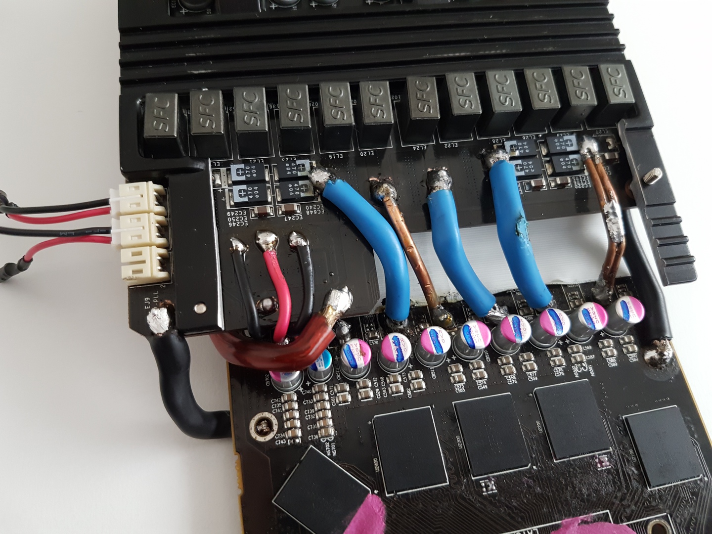
I would have left all 4 proadlizer caps intact but they were physically damaged so I removed them. This card had extensive physical damage but it was free so I dont mind missing the caps.i would cut the pcb like i did , with or without proadlizers cap , because is a good oportunity to use soldering joints to the vga target , directly from powercard pcb powerplane +and - VCC
you should add solid cap bank ( what you used now i don´t like it very much
, also added to much capacity of output filter will not help always ...because that change the behavior of VRM , and switching freq aswell( in some instances the fet´s will go more warm and chocke aswell ..because you will trigger the saturation current on them) ...so you need to add caps and test after.. ) also tantalum cap into place that allready missing on the stock filter!type and number of decoupling bulk requires is dependent of VRM design!
-
Hey,
I have a 580L that I am trying to make a power card from. I was able to get it working, the Vcore output is about 0.9v which I think is correct but it goes to zero volts with a load. Its at least partially working
The PWM is the same and the layout is similar to yours so I thought I would ask how you did it. Would you be willing to post a guide for how you got uP6225 working?
thanks!
have you managed to make it functional??
also have you measured before adding any supply voltage if there in the POR pins is allready signals? way you added voltage if the VTT pin has already? you only need to strap( soldering strap) manually the voltage ( 1.3-1.4v) to the EN pin and voila will work:)
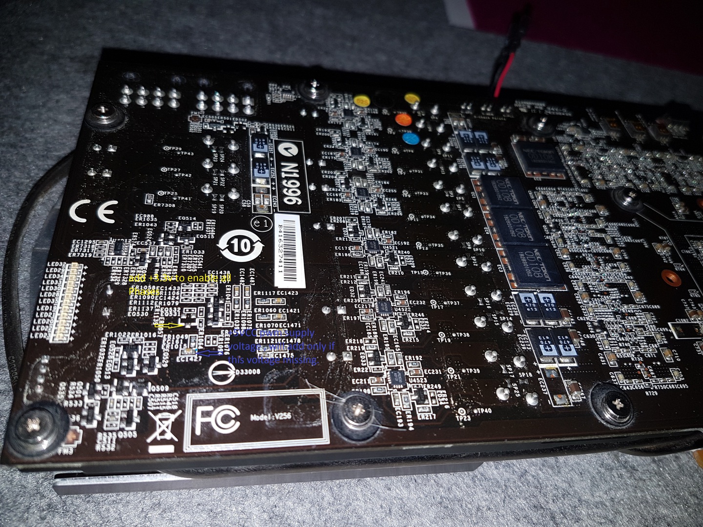
you need to add +3.3v only on the PSI pin ...to enable all pwm phases( all phase leds should lit) ...and the gDDR vrm will be activate aswell!!!
also you cuted the PCB and leave the gDDR proadlizer cap in the other side ? way you did that? also from gDDR vrm to soldering joints is way long traces , that filter(1000uF) will help you on transient current ..now it can´t do that anymore!
YOU WILL ADD FB TRIM ONLY WHEN POWERCARD IS MOUNTED ON THE LOAD. please not power on the powercard if you won´t removed the smd FB stock ressistor and replaced with trim pot!
i hope the pwm is still functional:D
-
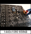
powercard is ready and allready instaled on hd7970 reference design
-
remove the EN , VTT and PSI +3.3v voltage .
hook up the powercard from psu pci-e cords and then measured these pins IF is any presence of voltage/signals on them , you will add +3.3v ONLY on the pins that missing signals!
EN pin will enable the chip if this pin are pulled hight , hight than 1.1v
VTT pin if is pulled hight , hight than 0.85v enable the controller!
-
i would like to add some tips at point 6.
you need to wait 10-15min only if the compressor electrical wiring is PSC ( Permanent Split Capacitor) that is using regular on the rotaryes but aslo you can use CSR ( Capacitor Start and Run)electrical wiring that is used usually on the reciprocating compressor in specially LBP(low back pressure) application , that mean heavyer start. because suction pressure will be near 0 bar or a bit above ..to archieve low evaporating temp!
R407c/R410a rotaryes are not designed for LBP aplication , they are for MBP/ HBP (medium/hight back pressure), that mean suction pressure will be at 5-7 bar so the start will be SOFT , so PSC wiring match perfect , but we phase changer convert the rotaryes into LBP application specifical for R404a/R507 so we will run the compresor near 0 bar to archieve low evaporating temp , but electrical wiring it using PSC ...that way you will need to waiting 15 min after start to start it again!
normaly we need to use CSR electrical wiring also on rotaryes , but that mean will add another cap and realy ..and that will rise the cost of unit!
-
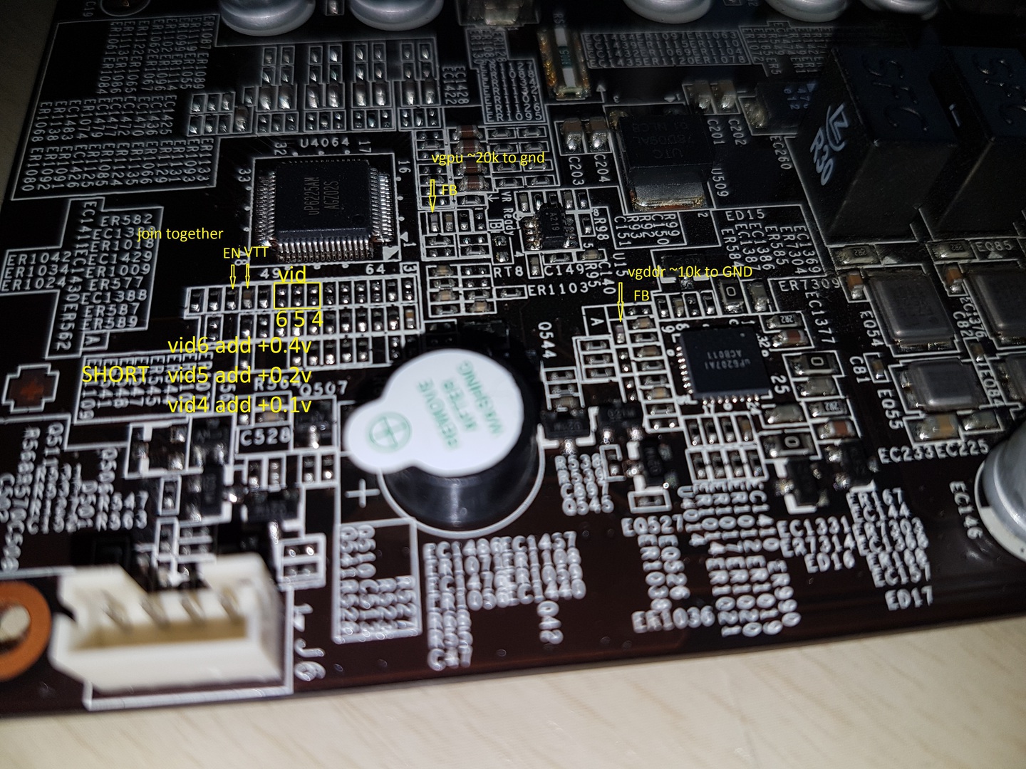
because i have time only in weekend , i configure the VID on this powercard .
like i said in my previouse posts VIDs is only way to pass OVP witch is a payn on many controllers
i add an 3 stepp dip switch :
position1 will add +0.1v (vid4)
position2 will add +0.2v (vid5)
position3 will add +0.4v (vid6)
also can be used together in combination at desired default voltage
for fine tune voltage i will add an FB trim pot and the card it have full voltage controll!
for DDR , FB default smd ressistor should be removed and replace with a 20k trimm pot !
to enable this pwm i joint together some pwm pins from POR internally circuity to add signals/voltage on them! also i simplified the wires on the front side because original heatsink will be cuted and remounted on the fets . wires from vid´s should be slim as posible for heatsink compatibility!
-
man that looks so awesome, I chipped my really nice 580 lightning gpu die trying to delid, would be so awesome to try this. Looks exactly like 580L power section
Yes it´s look like 580L power section , but pwm pcb traces are a bit different , but should be no problem to make it working , also i had here 2x580L , i can you helped if you want!
you should pay attention to POR(power on reset) module from pwm , that is the key to activated this pwm , also this time MSI implemented the "power state input for load" function ... i spend some time to find the right PSI pin to enable al phases ( see the leds)
i waiting the dip switches to make VID mod ( 0.1v ; 0.2v and 0.4v) to pass over all protection and then i ready:D
-
in fact i try to repair this card in oven ( you can see the buzzer plastic is a bit melted) ...but gpu was shorted(very low gpu ressistence) , also his gpu had 68 asic witch is potatto silicon quality to make some change in raking with ....i decided to use his vrm intro something really useful for an extreme overclocker:D
-
i think turning a lightning into an external power card ....because similar VRM you find on gtx 580 light witch you find on ebay even blind....
-
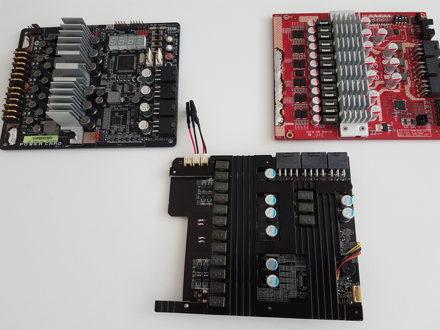
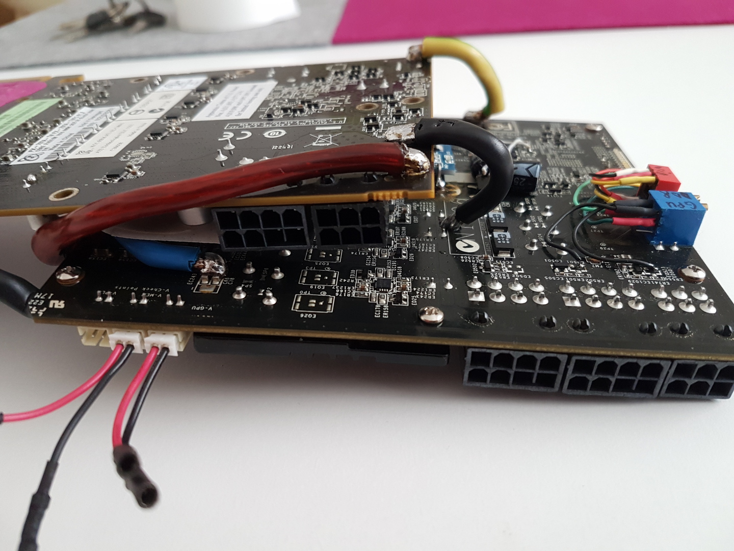
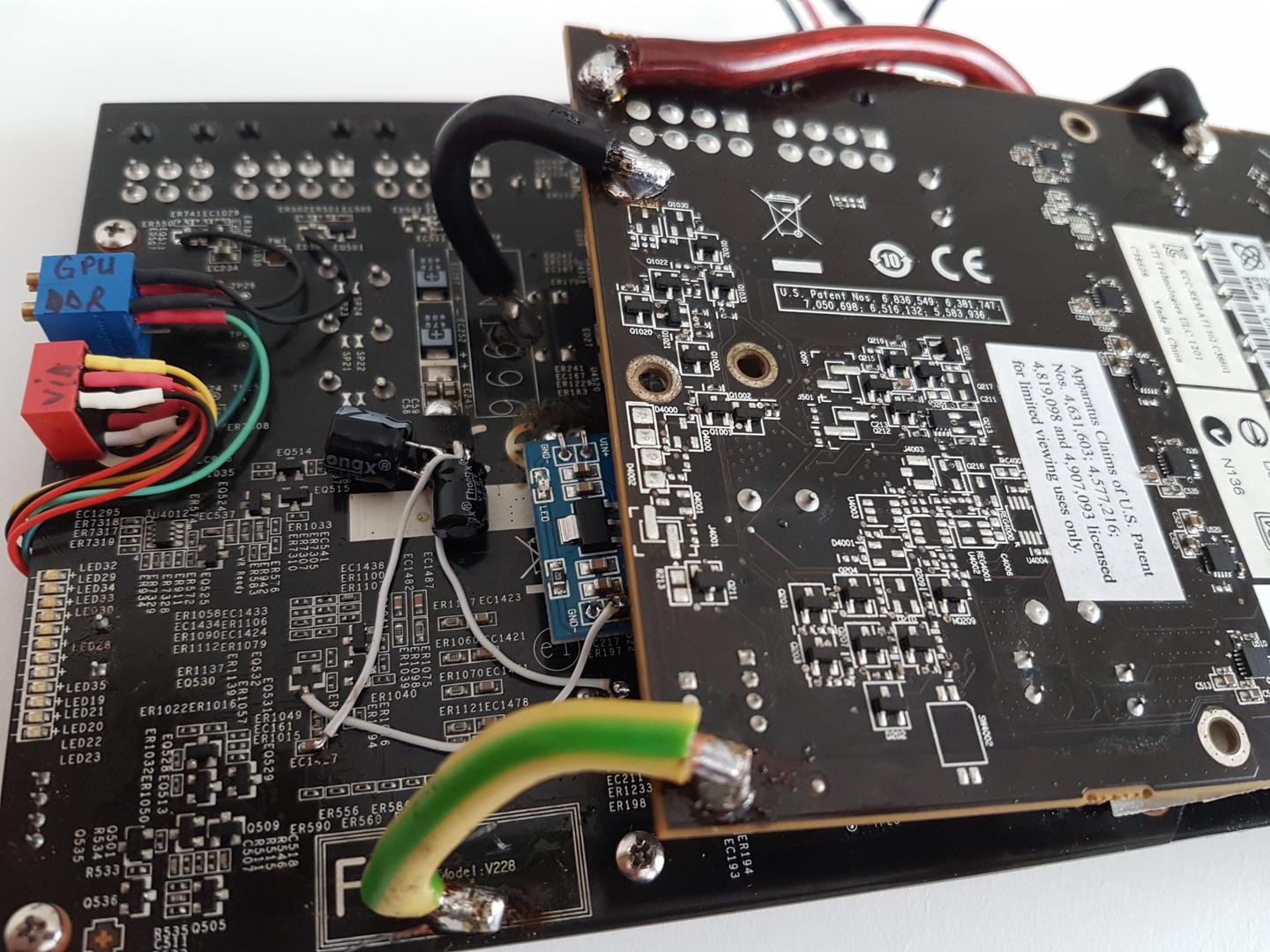
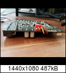
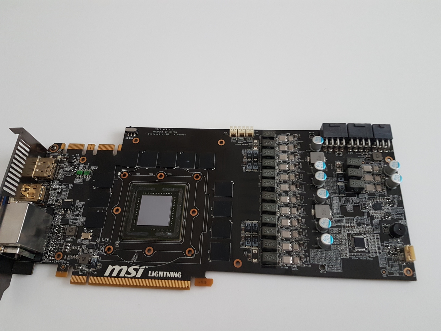
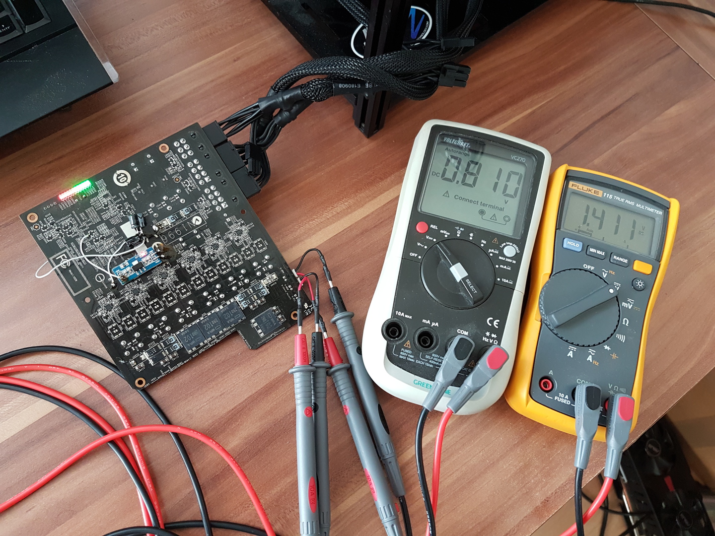
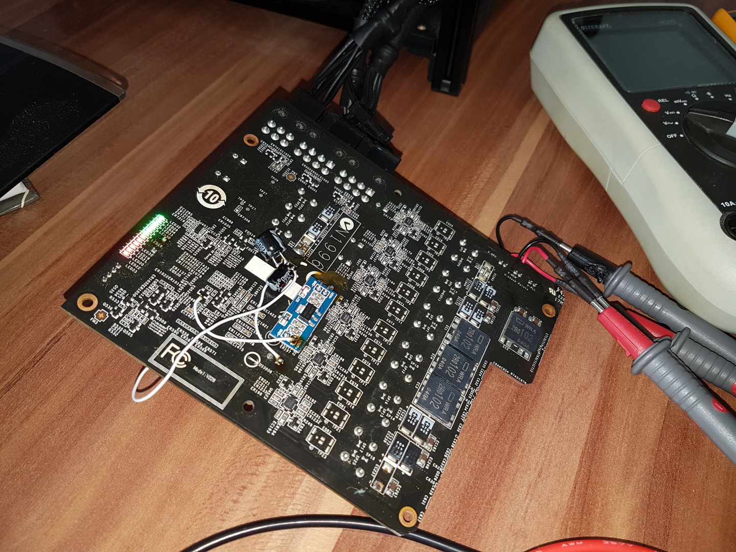
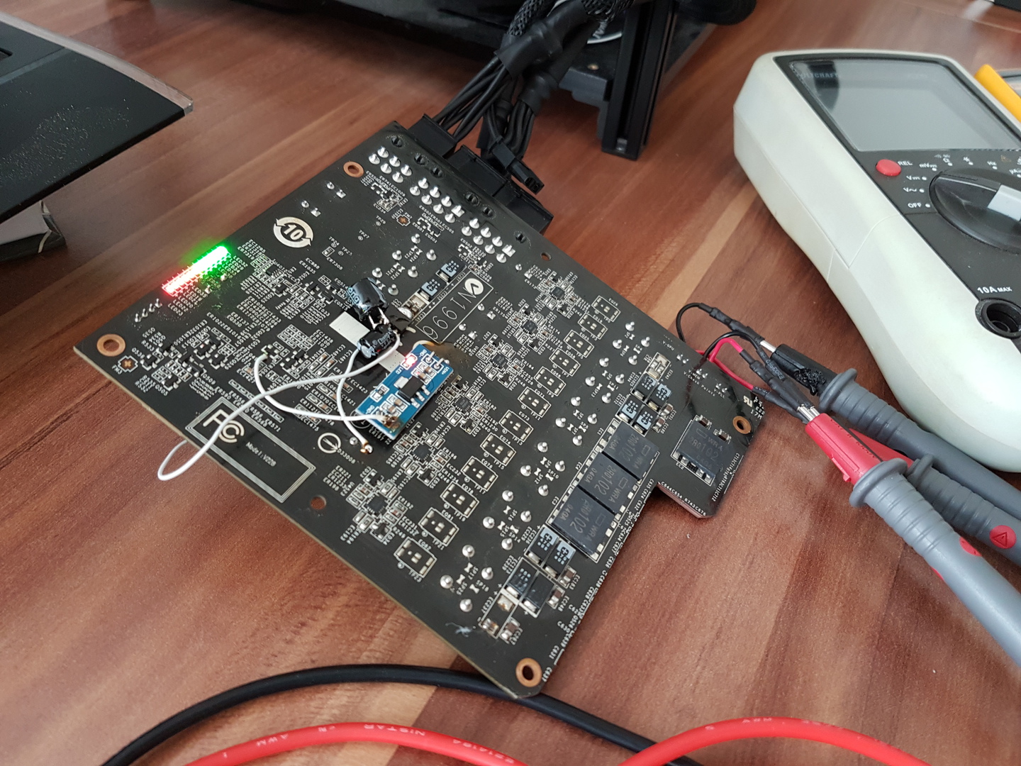
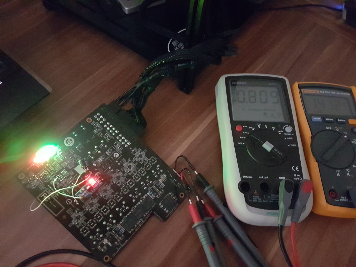
today i will show you another powercard from a dead GTX480 Lightning , it is a very powerfull card that can replace Epower or any vendor powercard!
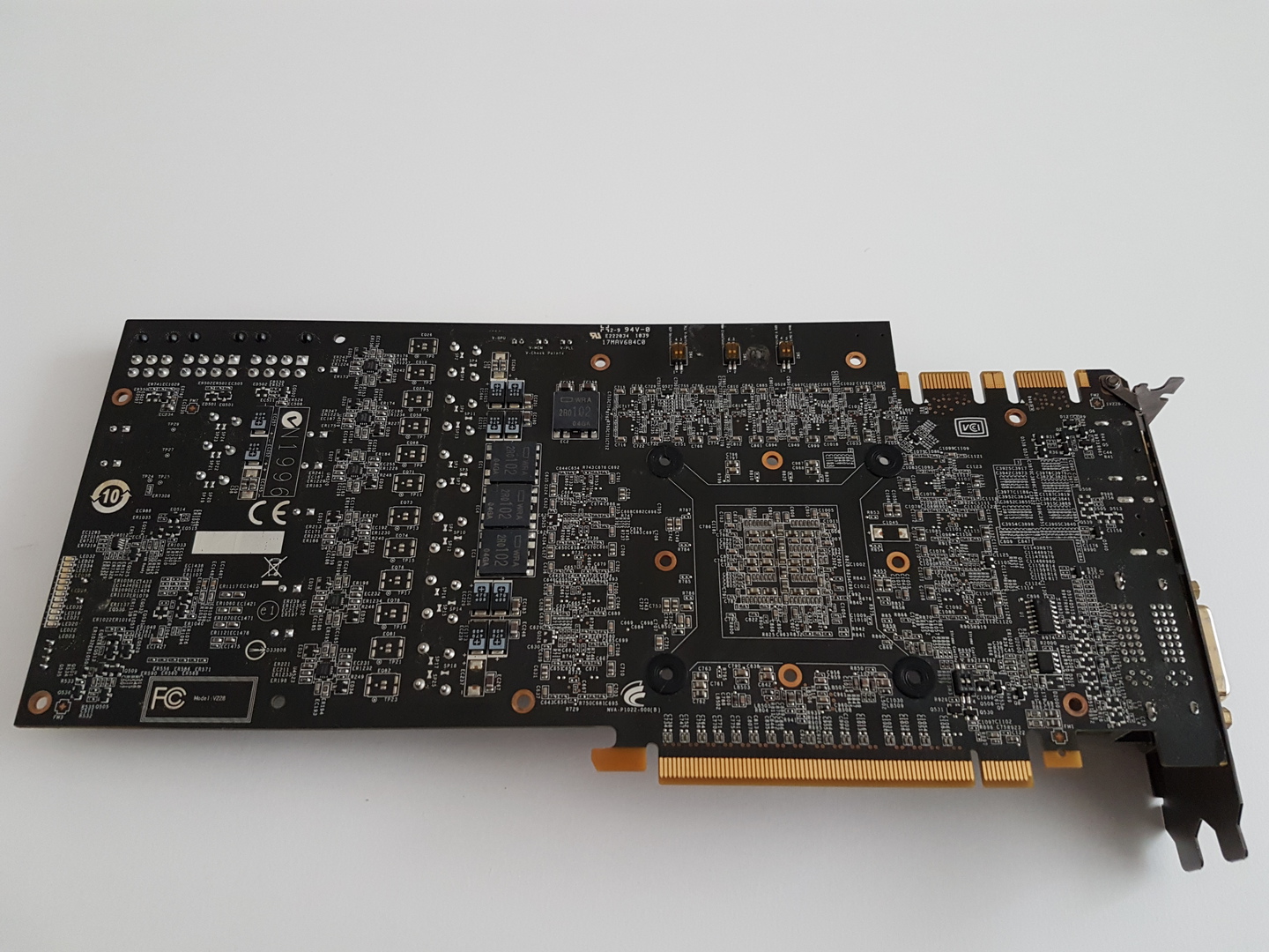
this one is a DUAL OUTPUT powercard , main pwm it is uP6225A , so it is a native 6 phases pwm , each phase are multplied by drivers uP6282AD , totaly 12 power phase! each phase are powered by IR6725/IR6723 Direct Fet package!
second pwm is uP6207AI it has 3 phase , each phase powered by IR6725/IR6721 DirectFet
output filter is full of tantalum caps and proadlizer( 3 for GPU and 1 for DDR)
it was not easy to see voltage on DMM because some pins are hiden under pwm package so i
cuted some traces and put together to simplified wires from LDO´s to main pwm !
enojoy!
-
 1
1
-
-
what resisstance you had with both 10k serial mounted from FB point to GND? should be near 1k value ! that means both trimmer poti are turned to max value ( both at 10k) for me seams you had used trimmer with less value than 10k both in serial!
from 0.85v default vddci voltage to 1.5v is lot of volts , you should give it max +350mv (1,2 -1.25v) if they scalling ...if not leave them alone!
first rule in modding , YOU check the default ressistance value from FB point to gnd , and after mod YOU check again ressistance value from FB point with trimm mounted to GND to be near the same ! THAN absolutly nothing bad can happend!
also make sure that "gnd" point you used is GND not something else! make sure that you measure the right VDDCI positive point not other
you had luck that pwm it has protection:D
-
3.3v LDO generate voltage for POR( power on reset).
-
push PLL voltage a bit prehaps will help with this issue!
-
Hi nachtfalke,
the gpu pwm ASP0907 is a uP6208?
Do you added +5v to supply the IC?
ASP0907 is up6208 or uP6225 both use same pin out!
yes, add +5vcc to pwm supply!
-
a friend of mine required my skill to mod his card , for a contest here on hwbot , for anybody intrested about hardmod , tested fully working!
i had no datasheet , so blind mode action:D
gpu pwm FB default value measured to GND is 2.8 Ohm
gDDR pwm FB default value measured to gnd is 1.024kohm


nachtfalke - Radeon HD 4890 @ 1370/1300MHz - 20630 marks 3DMark Vantage - Performance
in Result Discussions
Posted · Edited by nachtfalke
now i work in progress at the second cascade , much larger compressor size , and evaporator are 65mm diam( my designs ) , expansions valve are used another Id that works best for me , will be made with bypass valve and will be dedicated only for cpu cooling �