

hidethecookies
-
Posts
28 -
Joined
-
Last visited
-
Days Won
1
Content Type
Profiles
Forums
Events
Blogs
Everything posted by hidethecookies
-
Very nice
-
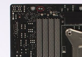
I need to find out a ganged resistor value on the x79 Rampage iv extreme. It's on the back, same corner as the bios code display. I'm missing one of them, the one remaining is a 272.
-
Help me to identify components on Palit 980Ti Jetstream
hidethecookies replied to Masterchief79's topic in Volt modifications
Its a Fairchild fdmf 6823a mosfet. Ebay has them. Ive seen people remove fried mosfets and the card would run on the remaining phases. It would not be ideal. There is probably a power good signal from the lower 4 phases that keeps the card from starting if its missing. -
Evga is currently (Nov2018) selling the $250 msrp Epower V for $99 on ebay in the usa. They still list it as msrp on their website though. https://www.ebay.com/itm/EVGA-EPOWER-V-100-UV-0600-BR/263766099046?epid=21019846172&hash=item3d69af4466:g:0PoAAOSwZ-Ba2ofi
-
I just bought a GTX 780 classified that was supposedly broken on ebay. I paid $60 and I planned on using it for a homemade epower. Seller stated PLL light was out which means that PLL vrm isn't functioning. PLL is a rather low volt and current vrm most cards are 1-1.25v at less than 5a. I figured I would try to put a little ebay 3a dc-dc buck converter I had for other zombie projects to power the PLL. If that failed then I would cut it in half and have an epower. When I got the card I noticed 3 missing smd caps and one resistor. I figured the caps didn't really matter but checked on Techpowerup hi-res picture for resistor size. It happened to be 0 ohm. I just used a small piece of copper wire and soldered it in. Then tested it out and it fired right up. I ran a few stress tests and oced a little. I can get 1350mhz @ 1.2v So is it worth keeping whole or just cut it up for epower??
-
Here's the diagram I made for it. I would like to add to the OP or previous post but I cant edit anything.
-
Repost lost pictures.
-
I was watching netflix on my htpc when I heard a loud pop. I'm not 100% sure where it came from but I automatically thought cap blowing. My pc has all solid caps though and they all are intact. I have a Maximus Gene VI with g3258, 580 classy, and older Corsair TX950 psu. The only problem I found was the 580s dual bios light. In normal mode its green and oc it turns red when all is good. Well my card was in normal mode but both lights were on. When I first noticed the red light was even kinda flickering. I restarted pc, unpluged psu for a min then restarted, and even reinserted gpu to no avail. It just stays red and green for normal bios and red for oc bios. I might try flashing the bios with a backup I have later today. I was hoping someone might have heard of it before.
-
I can't find definitive info on the solder pads on the 7970 matrix. I use the M6G and OC panel for VGA hotwire. I read on one forum about some MCU mod and special ln2 bios but all the links are dead or non existent.
-
So after some testing with a cheap GPU waterblock I managed 1430mhz or so on 1.35v. The vram for some reason doesn't like more than +100mv but I can get +600mhz OC. I'm just not sure how good those numbers are they are not the max for that voltage I just ran out of time to test further. I want to try more volts since I'm only hitting 43c load temp with one 420mm UT60 rad with 3 EK 140mm FF5 vardars. Just need some advice on Max volts for h2o cooling. I also want to test a few other gpus I have with the same setup 7970 lightning, 7970 matrix, and a 580 classy. Any advice for max volts for them would be helpful too. I will have to use VGA hotwire for the matrix to get more than 1.4v and I have ABX for the lightning.
-
I just got an Asus M6 Gene and OC Panel. I see alot of stuff on the web about vga hotwire but what can be done with the SMBus connection? I was thinking it might be used like elmors eVc but unsure of the OC Panels capabilities. My motherboard and OC Panel didn't come with any paperwork. Edit: OK I found a really good guide that explains all functions including smbus. It also shows how to hook it up to ref/dcuii/matrix 7970. I have the Matrix which is why I wanted this set up in the first place. The smbus lets you run the VGA power control app. The guide I found was written by Shammy over on KPC.
-
Haven't figured out the vmem yet and from the looks of others 480 zombies neither have they. I think there is a few signal, sense, or feedback lines that get cut and need replaced.
-
According to DS pvcc is output of internal 9v LDO. The pin provides stepped down current for gate drives. No need to supply power to it. It outputs about 10v when I feed vcc with 12. For some reason the controller is not fully enabled is there a way to test the gate driver?
-
Yeah I used a second DC DC converter to supply 5 volts. On my working 480 it was 12v so I tried that too. I not sure what the en pin is looking for I tried 3.3v. That's what I used for up1981 and chl8266. I have to recheck the working one. The card I cut was shipped to me untested with a full cover water block unmounted. They were not secured properly so the block beat the hell out of the card. It did not post so I just checked core voltage before the cut. It could be damaged somehow but looks good.
-
I can't seem to figure out the vmem output. I have a working 480 to test and the up6210 data sheet. I tried the usual add power to vcc and en but it's not working.
-
This one was easier than I thought a few people said it was hard and won't publicly share there work. I will though. All I did was look at the pinout of the chl8266 controller. The three 3.3v vcc pins 36, 28, and 3 are all connected to the same 3.3v plane. When power is added to the 3.3v power plane it powers all the pins needed. I just picked pin 36 traced to its capacitor and solder to it. The EN pin is 11 and this is where it got tricky because it goes strait to a via and buried trace. The cool thing about the 480&580 ref PCB there is a second controller pad that is not populated but all traces are there and hooked up. I just check continuity between pin 11 on the populated and unpopulated controller pad and it was 0ohm. That makes it easy to just solder straight to the empty pad. I used a small DC DC converter from eBay for 3.3v. I have yet to do an ocp or volt mod. I think I need to pull psi pin 16 high to make sure all phases are active though. I also used an old 570 ref heatsink and cut it for vrm cooling. Any questions just ask.
-
Well the card is dead but vrm is good that's why I'm asking in this section.
-
Anyone have experience with this card? On gigabytes website it shows world records once held by it and elmor had 2nd place 3dmark11 on ln2. It has 2 vrm controllers adp4100 for core, ncpxxxx for vram. Then it has a pic16f1937 not really sure for what though. I also thought the ncp controller looked big for 2 phase ram. It just has alot going on and a bunch of little chips too. I checked and the was 2 voltage comparators not sure what they do. The card doesn't display but the vrm is good just wondering why the chose such a complex PCB design.
-
Well I was waiting for the dip switch to show up and found out the 780 HOF voltage tool works for the 680. The sliders go to 2.3v core and +400mv vram. I only tested to 1.3v core so far on air. The tool is easily found with google. So no mods needed just like my 580 classy that can go to 1.8v with software just wish pll volts could be adjusted like the classy.
-
Looks like vid pins 2-5 are part out the connector pin out. I think I need to remove vid 6 resistor to go over 1.21 volts 😈 since its connected to power. The stock vid is 01000010=1.2 volts which is correct measured with dmm. I think I'm gonna do a multi dip switch setup. A vid mod will bypass bios limits right?
-
Lightning - Dual Output Powercard
hidethecookies replied to nachtfalke's topic in Volt modifications
The 6870 Hawk has the vram and pll phases on the left side of the card so I only have single output. Now I can use what was a dead card for something. -
Well it lookes like with a MSI hawk or Lightning card with the uP6218 you need to add 3.3v to PSI(power state indicator) pin 63 for all the phases to power on. I found a list of data sheets on xdevs. It includes the up6208 which has the same pinout as up1981/up6218 https://doc.xdevs.com/doc/_Datasheets/_DC_DC/
-
Lightning - Dual Output Powercard
hidethecookies replied to nachtfalke's topic in Volt modifications
i have a 6870 hawk that i got to work after cutting it in half. It outputs 1.289 volts but only one of the phase leds light up red. I'm not sure what it means. I used elmor's advice and did this Pin 26+48 = +5V supply Pin 51 = ENPWR (above 0.825V to enable controller) Pin 52 = ENVTT (above 0.825V to enable controller) Then after seeing this thread i was wondering about the PSI pin since all my phase lights are not on. EDIT: OK I figured it out but i needed 3.3v to VTT, EN, and PSI thanks for this thread I would have never figured it out. -
It says up1981a. Could it still have the same pin out since other 6870 Hawks have the up6218? Here is a comparison.
-
I have a MSI 6870 hawk I'm trying to turn into a power card/zombie. The vrm does not power on and I can't find datasheet for the controller its an up1681 I think. Is their some way to force vrm on or should I just cut it in half and go from there? UPDATE here is the card so far got it all figured out thanks to Elmor and Nachtfalke. So there it is 1.2v+ with all 8 phases powered up. It's way easier than I thought as long as your controller has a data sheet available or someone does the leg work for pins to turn it on. Update 2 I got some mini dc dc buck converters from eBay like others have. I also added GPU vmod. Now it is self contained no extra wires to PSU.

