

Tzk
-
Posts
229 -
Joined
-
Last visited
-
Days Won
9
Content Type
Profiles
Forums
Events
Blogs
Posts posted by Tzk
-
-
Great solution for the huge case switch. I might change my approach to this, too. Even shortens the code by reducing redundancy. Neat.
-
Doublepost:
And i tried to put the cylinder, sector etc. HDD items to good use. However some crash when you try to select an option (submenu opens but is empty and bios freezes instantly). I guess that you can't use them that easily.... So i stopped for now.
What i haven't tried up to now is the v4.35 BPL MSI uses on some bios, so that's next. I'm still struggling to get my 2x512mb TCCD Memtest stable at 245Mhz.
-
Can you try these two files to see if a) they work and b) if the settings are applied correctly? If you set everything to AUTO on the new Advanced Memory Settings menu the ISA option rom will be bypassed. Stock Settings at 200Mhz FSB are afaik:
- DriveStrength: 4
- Slewrate: 10
- Tref: 1560
- Trc: 13
- Trfc: 15
So you can try booting with values right next to these and have a look at R/Weverything and WPCRedit (B0D0F1 and B0D0F4) to see if these have any effect. If yes, then i did everything right and the mod works as expected. The two bios files are completely identical except Romsips (EBED vs. ED), both got v3.19 BPL and CPC on.
Note: As always these files are completely untested and may brick your board.
-
 1
1
-
I just tried to mess with the sector, landingzone etc display items... Looks like they aren't getting greyed out anymore when i change the function ID to FFFF. Interesting... ?
-
I guess i'm done with modding (for now). Everything works, custom items are added. Here's the files for A7N8X Dlx v2.0:
Also uploaded to bierbude: http://bierbude.spdns.org:2302/USER UPLOADS/Tzk/Asus/A7N8X Deluxe v2.0/
What's left to do is to port this over to A7N8X-E Dlx and to try to add more settings. Also the custom message upon boot looks very nice...
")
-
 1
1
-
1
-
-
So you want to basically the values which were set? Interesting idea. I also had another idea for Memtest: What if we include Memtest in the ISA option rom and start it from there? You could basically bypass or start it like we do with our "auto" settings.
And finally, here's my (ugly, but working) Tref code:
So all in all the bios works as expected and i'll upload it somewhere. Next, i'll see if i got some other items in bios left to (re)use. Maybe we can add the alphatimings.
-
Regarding the XOR:
xor ebx,ebx ; clears ebx with zeros mov bl,al ; moves al -> bl movzx ebx, al ; move with zero extend ; moves al -> bl AND sets all other bits of ebx to zeroSo you can basically use movzx instead of xor+mov.
Using a mask inbetween is smart. I'll do that in the exact same way as it saves a bit of code.
-
Looks good. However i do not get how you're setting two registers and a single register with the same data (ebx). Shouldn't this also set undesired registers, eg. 7F and 7D instead of only 7D? Or are you masking the old value and the new data in ebx before applying it?
-
I just doublechecked a DFI LPB bios with modbin. DFI allows Trc = 31T and Trfc = 31T. Same for NF2 Tweaker. I've been testing these at 100Mhz because at this low clocks you can do Trc 7 and Trfc 8 easily and without data corruption.
I've had errors in fasmw when using mov ebx,al. That's why i switched to using either registers of same size (mov bl,al) or use movzx eax,al. The last one fills all other bits of the eax register with zeros and thus cleans any leftover data on that register. I also ended up building a huge switch table for Tref. Will test now and upload when it works.
Here's my code for DS and SR. I had to read cmos twice on each of these for this because ebx and al are used inside the writeregister macro and thus i have to re-read them to set the second set of registers. Maybe you got a better idea for this.
;read drive strength readcmos 75h, 0F0h ; read cmos and write to al cmp al, 00h je drivestrength_end ; jump to next setting if auto selected (equal 0000.0000) shr al, 4 ; al now: 01h movzx ebx,al ; ebx now: 000000001h shl ebx, 4 ; ebx now: 000000010h add bl,al ; ebx now: 000000011h shl ebx,8 ; ebx now: 000001100h writeregister 08000047Ch, 0FFFF00FFh ; offset 7D writeregister 080000480h, 0FFFF00FFh ; offset 81 readcmos 75h, 0F0h ; read cmos and write to al shr al, 4 ; al now: 01h movzx ebx,al ; ebx now: 000000001h shl ebx, 4 ; ebx now: 000000010h add bl,al ; ebx now: 000000011h shl ebx,12 ; ebx now: 000001100h add bl,al ; ebx now: 000011001h shl ebx, 4 ; ebx now: 000110010h add bl,al ; ebx now: 000110011h shl ebx,8 ; ebx now: 011001100h writeregister 080000464h, 000FF00FFh ; offset 65 and 67 writeregister 080000470h, 000FF00FFh ; offset 71 and 73 drivestrength_end: ; jump target ;==================================================================== ; read Slew rate readcmos 75h, 0Fh ; read cmos and write to al cmp al, 00h je slewrate_end ; jump to next setting if auto selected (equal 0000.0000) movzx ebx,al ; ebx now: 000000001h shl ebx, 4 ; ebx now: 000000010h add bl,al ; ebx now: 000000011h writeregister 08000047Ch, 0FFFFFF00h ;offset 7C readcmos 75h, 0Fh ; read cmos and write to al movzx ebx,al ; ebx now: 000000001h shl ebx, 4 ; ebx now: 000000010h add bl,al ; ebx now: 000000011h shl ebx,12 ; ebx now: 000011000h add bl,al ; ebx now: 000011001h shl ebx, 4 ; ebx now: 000110010h add bl,al ; ebx now: 000110011h writeregister 080000464h, 0FF00FF00h ;offset 64 and 66 slewrate_end: ; jump target ;====================================================================
And these are the macros i use for readcmos and writeregister, as posted several times on this thread:
;==================================================================== macro writeregister pcireg, cmask { mov eax,pcireg ; move address for 32bit register offset mov dx,0CF8h ; pci register address port out dx,eax ; set port we want to read mov dx,0CFCh ; pci register data port in eax,dx ; read register values and eax,cmask ; mask for data to remove pre-set value, usually the inverse of the data we set or eax,ebx ; add custom value to old register data out dx,eax ; write new custom register value } ;==================================================================== macro readcmos cmosreg, mask { mov al, cmosreg ; set cmos register out 072h, al ; send register offset in al, 073h ; fetch data and al, mask ; mask al to discard last 4 bits as these are used for slew rate } ;==================================================================== -
Good spot. Fixed number 4.
Yes, DFI somehow thought it's a great idea to group the refresh rates by refresh cycle time. That's why they got 1.95us, 3.9us, 7.8us and 15.6us groups and each of these got 4 options: 100/133/166/200Mhz. Interestingly 100MHz 15.6us hasn't got the same count of cycles as 7.8us 200MHz which is weird. That's the same for other values, too...
-
Your code looks great!
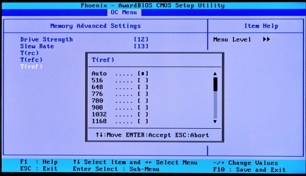
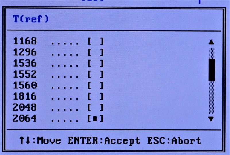
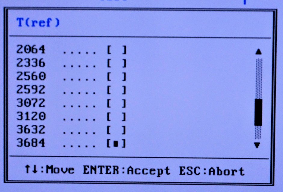
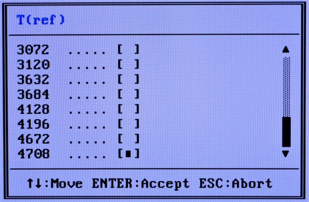
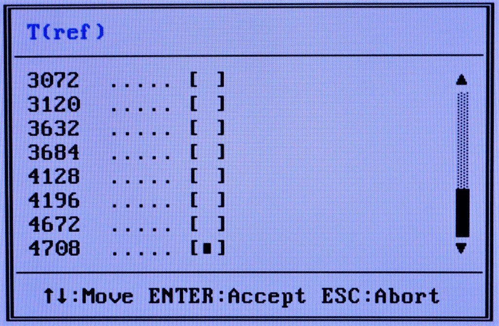
I just got DS, SR, Trc and Trfc working, all of them without case switching. Next is Tref, however my guess is that this isn't doable without switch table as we can't map the input from cmos cirectly to hex values. This are Tref values i'll implement:
; 00: Auto (keep value, skip custom code) ; 01: 0402 -> 0204h = 516 cycles ; 02: 8802 -> 0288h = 648 cycles ; 03: 0803 -> 0308h = 776 cycles ; 04: 0D03 -> 030Dh = 780 cycles ; 05: 8C03 -> 038Ch = 908 cycles ; 06: 0804 -> 0408h = 1032 cycles ; 07: 9004 -> 0490h = 1168 cycles ; 08: 1005 -> 0510h = 1296 cycles ; 09: 0006 -> 0600h = 1536 cycles ; 0A: 1006 -> 0610h = 1552 cycles ; 0B: 1806 -> 0618h = 1560 cycles ; 0C: 1807 -> 0718h = 1816 cycles ; 0D: 0008 -> 0800h = 2048 cycles ; 0E: 1008 -> 0810h = 2064 cycles ; 0F: 2009 -> 0920h = 2336 cycles ; 10: 000A -> 0A00h = 2560 cycles ; 11: 200A -> 0A20h = 2592 cycles ; 12: 000C -> 0C00h = 3072 cycles ; 13: 300C -> 0C30h = 3120 cycles ; 14: 300E -> 0E30h = 3632 cycles ; 15: 640E -> 0E64h = 3684 cycles ; 16: 2010 -> 1020h = 4128 cycles ; 17: 6410 -> 1064h = 4196 cycles ; 18: 4012 -> 1240h = 4672 cycles ; 19: 6412 -> 1264h = 4708 cyclesAnd here's my isa option rom (without Tref) i currently use:
-
The Code above is almost the same AS the macro from the ASM code i uploaded a few days ago. No major changes.
I was aware that al and ah are inside ax and inside eax. I wasn't aware that i can store data in ax and use eax afterwards while keeping the data. Makes it a bit easier to handle instead of numerous bitshifts.
I haven't finished the option rom yet, will upload the completed code when IT works.
-
So if i got you right, then this should work to set Trc, correct? I use 00h as "auto" and then every value is passed cirectly from al to ebx which is my data register.
So this is bacially a switchless and compact solution for Trc and Trfc.
;==================================================================== ; set trc mov al, 76h ; read index - 76h out 072h, al ; send register offset in al, 073h ; fetch data and al, 1Fh ; mask al to discard first 3 bits cmp al, 00h je trc_end ; jump to next setting if auto selected (equal 0000.0000) ; mov eax,080000190h ; move address for 32bit register offset mov ebx,al ; move data we want to set mov dx,0CF8h ; pci register address port out dx,eax ; set port we want to read mov dx,0CFCh ; pci register data port in eax,dx ; read register values and eax,0FFFFFF00h ; mask for data to remove pre-set value, usually the inverse of the data we set or eax,ebx ; add custom value to old register data out dx,eax ; write new custom register value trc_end: ; jump target ;====================================================================Trc is B0D0F1 offset 90h while Trfc is 91h. So i inset a left shift by 2 bits on Trfc right after the data is set, correct?
;Trc (90h): mov eax,080000190h ; move address for 32bit register offset mov ebx,al ; move data we want to set ; no left shift here mov dx,0CF8h ; pci register address port ;==================================================================== ;Trfc 91h: mov eax,080000190h ; move address for 32bit register offset mov ebx,al ; move data we want to set shl ebx,2 ; leftshift by 2 bits (011h -> 01100h) mov dx,0CF8h ; pci register address port -
That's what i did too.
I started with the stock 1007 Asus bios, moved items with modbin, relabeled them, edited en_code.bin, swapped romsips and BPL. I just opted to create a new item label group to have everything in a single place. So there are some unused labels now in some label groups which the bios originally used before i made my changes.
-
Here's how i did it. My item labels are at the very end of en_code.bin and my item strings and mapping for the option rom are in the textfile. Maybe this saves some work on your end?
I haven't written the actual code for the isa option rom yet, that's the next thing i'll do.
-
1
-
-
I'll also stick to two bios versions for CMD. We'd probably need to hook into the bios code way earlier to make it work. As we just need to swap BPL that's the easiest option. And besides that i can only think of a single case when you'd need 2T anyways: max fsb and max mhz runs. For everything else 1T is better.
For Tref we must use a big switch... You can't map a Tref value like 4708 (cmos register will contain 1Ah) properly to 6412h through math. So it's simpler to just store the value inside the option rom and use a huge switch. For Trc, Trfc, DS and SR it'll work with math. I mapped Auto to 00h and 1 to 01h. For DS and SR 15 to 0Fh and for Trc and Trfc 31 to 1Fh.
I haven't messed with the IDE values yet and will possibly do this when i got Trc, Trfc and Tref working.
-
I like your thinking... Do these values look somewhat familiar?

I opted to not use values below 516 as even at 100Mhz (DDR200) the default value for 7.8ns ram is 780 cycles.
-
So setting CMD after POST is a nogo then.
I finally decided to switch my bios settings from data scavenged rate, superbypass and autoprecharge to Trc, Trfc and Tref. i already got them working in bios, next is the option rom. So i got Data strength, slew rate, Trc, Trfc and Tref in bios.
Still i haven't managed to add new settings and i fear it's just too complex to get it done on the compiled bios. So i'll try to recycle other bios options next. Have you tried to for example use the Cylinder, Head, Sector and Landing Zone (display) fields of the harddrives? I got 20 items in total for this... (5 items for 4 drives each).
-
87: 03
99: 31
9A: 65
F9: 45
Used my modded bios on A7N8X DLX v2.0 with BPL3.19 1T taken from Taipan 0.3 bios.
-
1
-
-
And a thought regarding the Tref:
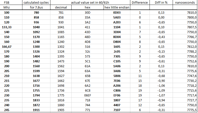
Shouldn't the refresh time (in nanoseconds) stay the same when we use different dram clocks? I guess that Tref is set in clocks (not time), so when changing fsb it should also change. Various dram chip datasheets state that Tref must be ~7.8us ( =7800ns). So if we calculate how many clocks it takes to last 7.8us at a given frequency, then we should find Tref, no?!
200MHz = 5ns -> 7800ns / 5ns = 1560 clocks -> 618h
166Mhz = 6ns -> 7800ns / 6ns = 1300 clocks -> 514h
133Mhz = 7.5ns -> 7800ns / 7.5 = 1040 clocks -> 410h
100Mhz = 10ns -> 7800ns / 10ns = 780 clocks -> 30Ch
I dumped all chipset registers with WCPRedit at different FSBs while i kept all other settings equal (multi, volts,....). I used the Asus stock 1008 bios with 3.02BPL. And i think i found something: B0D0F1 (the function which does also store the alpha timings) at offset 60h and 61h. I assumed little endian notation:
200Mhz: 1A06h -> 061Ah -> 1562 (clocks?!)
166Mhz: 1605h -> 0516h -> 1302
133Mhz: 1104h -> 0411h -> 1041
100Mhz: 0D03h -> 030Dh -> 781
Looks VERY similar to above, doesn't it?! So, i conclude that offsets 60 and 61 may be Tref
I tried several values (100Mhz to 245Mhz in small steps) and plotted everything. Here's the result for my A7N8X. It's very interesting to see that Asus actually increases the time between refreshs at 100/133/166/200Mhz. These are visible as the four highest points on the grey curve. And it looks like Asus does more refreshs above 200mhz with the most refreshs occuring at ~225Mhz. Above that they're decreasing the refreshs again. The (JEDEC) standard value for ddr1 is 7800ns, while more refresh should increase stability but decrease bandwidth.
/
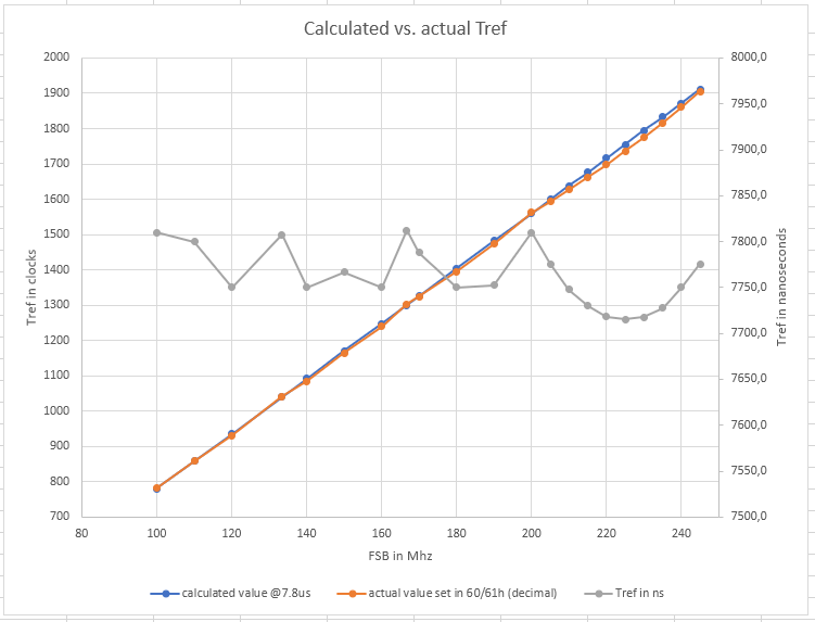
I noticed that some people use way higher values on S.939. On my Asus i got 1560 cycles at DDR400 while some users on DFI Ultra-D use 3000 to 4000 at DDR600. That'd translate to 2000-2600cycles at 200Mhz. So there might be performance left, depending on the exact chips we use.
Here's the data for the diagram, i also calculated the absolute and relative delta between actual and calculated value per frequency. What matters most are the first three columns though.
-
2
-
2
-
-
Very nice, congrats! Looks like my effort to document everything paid off already.
I'm still investigating if it's possible to add new items. Luckily Asus increased the number of bios items when going releasing newer bios versions. 1006 got 212 items, 1007 213 and 1008 has 214 items. But (and that's the bad part): the system.bin changes are all over the place. It looks like the code interacts heavily with the items, the item offsets and the misterious codeblocks in front and directly after the item strings.
It looks like even a single added items string shifts a lot of offsets in the code as the following strings and mysterious blocks are moved by 25bytes. There are also changes inside those blocks which is why i think those blocks aren't neccessarily code, but some kind of lookup table (just like the label groups in _EN_CODE.bin). However i'm currently not able to see any scheme on how this was done. It's either too complex to understand it while looking at hex files or the changes are done at several places simultaneously which will make it almost impossible to tweak the hex file by hand to get new items.
If only we had the sources of those bios files...

EDIT:
What about the Head, Landing and Blocks items you see when you select the submenu for drives? Do we need these? That'd give us 10+ items to work with.
-
1 hour ago, I.nfraR.ed said:
If we could find how to add new items then it would be perfect, but works this way, too.
Yep, that's the only thing missing to be able to fully customize the bios. I'd love to add a ton of items just like on the DFI bios... I even wondered what happens if i try to port some of the bios item blocks (those confusing code blocks + the item strings) from DFI to Asus...
No clue if the Gigabyte is a decent board. I guess you'd have to mod a bios for it anyways as there are only a few modbios available.
-
It basically doesn't matter which option is listed first. You can specify a default value for both "load optimised defaults" and in case the cmos was cleared. So Auto doesn't need to be 00h. I just did this for convenience and to have Auto listed as first (topmost) option on all items in bios.
You could possibly simplify the code on the DS and SR settings by just reading the cmos value and applying it directly onto the data register. Maybe with a bit shift to fill all neccessary bits. So basically:
- read cmos
- use helper variable to store setting
- apply helper variable to data register (ebx)
- bitshift helper, apply again (repeat if neccessary)
- then apply data as before onto desired pci register
This would, if done smart, fully eliminate the need for the huge compare+jump table. Except for the auto settings (which is still 00h and should be applied anyways).
I'm not sure if it's worth to mess with the settings which got only few options anyways (auto precharge, DSR, SuperBypass). However the slewrate and DS settings would significantly reduce the filesize.
-
Correct. You only need to specify the heading label and the first selection on the lookup table of the label group. If you got 5 bios items you want to fully label, then you'll have 10 pointers on the label group: 5 pointers for the heading labels and 5 pointers for the selectable options. The bios will handle reading the other available selections via the # of selections on the bios item string in system.bin. And this is the reason why all selection labels must be of equal length.
The two empty lines (offset 5A60 and 5BE0) are just for padding and to make it a bit easier to read. You could just leave them out. However that'd obviously change your label position and thus the pointers on the lookup table.
If you need to padd the selectable options themselves then use 20 instead of 00. You only got 00 directly in front of the start of a label.

A7N8X-E Deluxe as an alternative for socket 462
in Mainboards
Posted · Edited by Tzk
I've read about FASMs struc and struct which both seems to be some kind of data structure: https://board.flatassembler.net/topic.php?p=193530
Taken from the links:
;declare
struc my_struc 1,2,3,4,5,6,7,8,9,A,B,C,D,E,F {
 		.1 dw 1
        .a dw a
		(.....)
		.F dw f
}

;instantiate
my_label my_struc 0x3456,0x9876,'X','r'

;access
mov ax,[my_label.a]
Question is if we can choose the label based upon the register value. So you'd instantiate the struc with the Tref values in the correct order and just use the cmos value as pointer to the data values in struc.
If this works, struc is more or less a one-dimensional array (or let's say "list") of items.