I.nfraR.ed
-
Posts
2473 -
Joined
-
Last visited
-
Days Won
36
Content Type
Profiles
Forums
Events
Blogs
Everything posted by I.nfraR.ed
-

Splave - Core i9 10980XE @ 5872MHz - 5908 cb Cinebench - R15
I.nfraR.ed replied to flanker's topic in Result Discussions
It can be only one thing - running some light load on the cpu while not benching. Perhaps stops automatically when higher load (above certain threshold) is detected. -
A7N8X-E Deluxe as an alternative for socket 462
I.nfraR.ed replied to TerraRaptor's topic in Mainboards
There are some results (numbers) he shared at the end of the first post on the linked page, but I'm skeptical about that, maybe something is/was completely broken on the MSI from the beginning. Sadly, pictures are gone. https://forum-en.msi.com/index.php?topic=84715.90 -
A7N8X-E Deluxe as an alternative for socket 462
I.nfraR.ed replied to TerraRaptor's topic in Mainboards
The v4.35 has tighter timings (primary and secondary/alpha), that's why it is not compatible with many sticks. Perhaps something else, too. I've read the changelog of B72c from BOSSKILLER and there are things I don't know how to do: Will have to compared to unmodded bios (or the previous B62). There are more items missing in the Advanced BIOS Setup screen in the NF7 bios. CPU L1 Cache and CPU L2 Cache are showing in modbin and everything with the items seems fine in the system bios, but they don't show up runtime, just like the EPA Logo option. Trying to figure out how to fix this. -
A7N8X-E Deluxe as an alternative for socket 462
I.nfraR.ed replied to TerraRaptor's topic in Mainboards
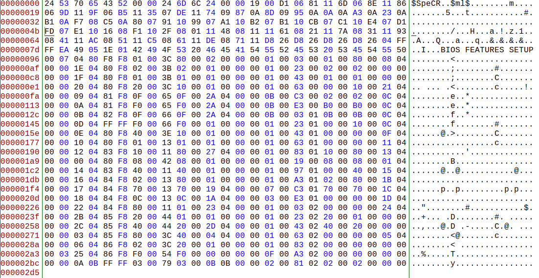
I'm trying to make use of some existing items for custom option. NF7 bios has Small Logo (EPA) option in Advanced BIOS Features setup screen. However, it is only visible in modbin and not in the actual bios. It is set to "visible" and the default option is "Disabled". Original option looks like this 00 00 02 04 89 F8 40 00 3E 40 00 01 00 00 00 01 00 C3 02 00 00 00 00 00 00 So I have moved it under the rest of the custom options and since I still have SuperBypass labels, decided to connect them to the option. Modded item is basically the next item from the custom labels, with it's 3 options, mask and cmos register. 00 00 0A 0B FF FF 03 00 79 03 00 0B 0B 00 00 02 00 81 02 02 00 02 00 00 00 Modbin shows it correctly - labels are the correct ones, default option is selected, position in the menu is correct. But after flashing the bios and going to the setup screen, the option is still not there. It is still hidden/removed, but this time the broken EPA logo shows in the right top corner. So I kind of disconnected it, but can't use it, since some subroutine from bios code hides it/deletes it. The ID is changed, but I can't move it to other place in the binary. Next item starts with 0x20, which according to the struct I've posted on the previous page is "PMITEM", whatever that means. 20 00 EB 0E FF FF E0 00 63 E0 00 09 0F 00 00 04 00 2D 00 00 00 00 00 19 00 Here's what I think is the whole advanced bios features setup screen, or at least significant part of it. Not sure if the $SpeCR %ml$ heading is the start of the setup screen or the end of the previous one. Most of the labels are similar, my modded one starts at 0x2bc - the last one. There's only one with FF FF in column 5 and 6 - in offset 0x145. Also 2 items don't have 00 in second column - offsets 0x96 and 0x2a3. Wonder what this is... Edit: This 0x3 in the second column means a KEY_IN item, I think. This is is a popup menu for the previous option "Delay IDE Initial" with options from 0 to 15.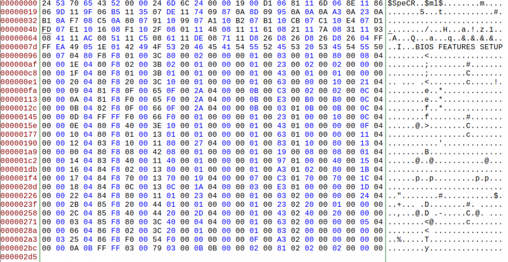
-
A7N8X-E Deluxe as an alternative for socket 462
I.nfraR.ed replied to TerraRaptor's topic in Mainboards
It's a little cleaner, but has one additional jump. It probably gets compiled to almost the same thing in both cases anyway. I was searching for a "table" solution, there's this thing called jump table, but I didn't understand it 100%. Ideally I would want something like this - an array or a key-value pair, etc. But I don't know how to do that in ASM. const setTrfc = val => { const trfcTable = [0x0010, 0x0020, 0x0040 ... 0x1264]; const value = trfcTable[val]; writePciReg(...); }; const cmosValue = readCmosReg(0x77); (cmosValue > 0) && setTrfc(cmosValue); -
A7N8X-E Deluxe as an alternative for socket 462
I.nfraR.ed replied to TerraRaptor's topic in Mainboards
There's my option rom. I've fixed tRC to support up to 31 and switched SR and DS. Added the full list of options for tREF. Everything works as expected. PS: Too bad we can't use the IDE options. So the modding kind of ends here. If only we had separate _ITEM.BIN... The only thing left to try is integrate memtest as an ISA option ROM and control it with some menu item, e.g. EPA logo if you have that in the bios. NF7_ISA_OROM_v1.ASM -
A7N8X-E Deluxe as an alternative for socket 462
I.nfraR.ed replied to TerraRaptor's topic in Mainboards
The Option ROM message works, but I guess the code executes too fast to show something. Removed the far return to bios and it now displays it. I will need to add some artificial delay to make it visible. -
A7N8X-E Deluxe as an alternative for socket 462
I.nfraR.ed replied to TerraRaptor's topic in Mainboards
The message is nice, but nothing shows on the real machine Will get the tREF done, fix tRC range and that will be for now. Then port it to AN7, should be able to just copy and paste most of the things. -
A7N8X-E Deluxe as an alternative for socket 462
I.nfraR.ed replied to TerraRaptor's topic in Mainboards
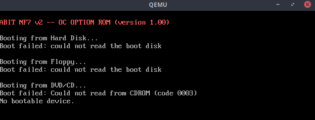
Works in QEMU, will test on the mobo in the evening code end codeend: popa popfd ; return far to system bios routine retf print_string: ; Routine: output string in SI to screen mov ah, 0eh ; BIOS tty Print xor bx, bx ; Set display page to 0 (BL) jmp .getch .repeat: int 10h ; print character .getch: mov al, [cs:si] inc si test al, al ; Have we reached end of string? jnz .repeat ; if not process next character .end: ret ; String ends with 0x0d (Carriage return) and 0x0a (linefeed) to ; advance cursor to the beginning of next line text_string db 'ABIT NF7 v2 OC OPTION ROM v1.00', 0dh, 0ah, 0 ; use 00h as the padding bytes until we reach the ROM size ; The last byte (512th) will be the patch_byte for the checksum ; patch_byte is calculated and automagically inserted below times (ROM_SIZE_IN_BYTE-$) db 0 PREV_CHKSUM = 0 repeat $ load CHKSUM byte from %-1 CHKSUM = (PREV_CHKSUM + CHKSUM) mod 0x100 PREV_CHKSUM = CHKSUM end repeat ; store the patch_byte store byte (0x100 - CHKSUM) at ($-1) call of the print routine MAIN: ; save all registers for later restore pushfd pusha mov si, text_string ; Put string position into SI call print_string Got the print code from stackoverflow: https://stackoverflow.com/questions/49001298/option-rom-code-failing-to-print-intended-string-using-qemu-emulation Perhaps we can simplify the code by using call instead of near jumps. Basically define all SET functions at the end of the ROM, read CMOS for each setting and if not 0 (Auto) call set_timing. Edit: no NIC ROM to reduce clutter qemu-system-x86_64 -net none -option-rom NF7_OPTION.BIN Now with color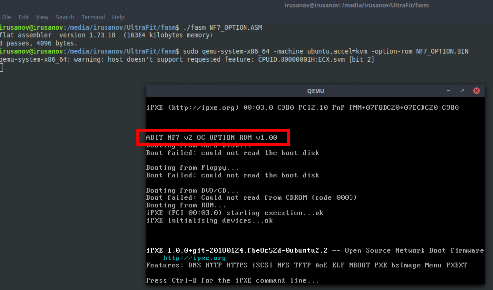
-
A7N8X-E Deluxe as an alternative for socket 462
I.nfraR.ed replied to TerraRaptor's topic in Mainboards
At least it is perfectly readable. I don't know how to optimize that, so will probably use your code, since I was going to write the same long "switch". For any other setting I want to use the direct value, yes. For DS and SR we need "doubling" the bits, so the direct value e.g. A turns into AA. Don't know if there's a more efficient/shorter way of doing it compared to the bitshifts I'm currently using. I would do it the same way on C++ or javascript. That's where my knowledge for bitwise operations ends All in all, I think we got the code on the "next" level, compared to the patch ROM of tictac for example. We now have fully functional bios items, while his code only sets things unconditionally. The memtest idea could work. Control if it runs with an option in bios (you can use EPA logo, for example). -
A7N8X-E Deluxe as an alternative for socket 462
I.nfraR.ed replied to TerraRaptor's topic in Mainboards
And I will use the movzx I also experimented with printing text from the ROM to the screen and it worked, but I did something wrong with the return, since it was stuck at it and didn't continue. One more day and we will have everything working, then I will try again. PS: so maybe xor ebx, ebx mov bl, al is actually a little bit faster, although I'm not sure if the compiler optimizes it further. Maybe check compiled binary in both cases. -
A7N8X-E Deluxe as an alternative for socket 462
I.nfraR.ed replied to TerraRaptor's topic in Mainboards
Yes, I mask ebx before setting it, but it's in the code at home. Sorry about that. Same for slew rate. writePciReg 0x80000464, ebx, 0x00FF00FF ; 67, 65 writePciReg 0x80000470, ebx, 0x00FF00FF ; 73, 71 and ebx, 0x00FFFFFF ; <-- here writePciReg 0x8000047C, ebx, 0xFFFF00FF ; 7D writePciReg 0x80000480, ebx, 0xFFFF00FF ; 81 -
A7N8X-E Deluxe as an alternative for socket 462
I.nfraR.ed replied to TerraRaptor's topic in Mainboards
Yes, I copy al to bl or bh, depending on the situation. mov bl, al will replace the whole bl with what is inside al. Don't know which method for clearing (zero-ing) ebx is best and most efficient one. Currently using xor ebx, ebx Here's my code for drive strength and slew rate with some comments. set_slew_rate: ; read slew rate from CMOS readCmosReg 0x78, 0xF0 ; for example cmos data is 7 -> al is 0111 0000 ; need to set 0,0,4 reg 64, 66, 7C cmp al, 0 je set_drive_strength ; else xor ebx, ebx mov bl, al ; bl is 0111 0000 shr bl, 4 ; bl is 0000 0111 or bl, al ; bl is 0111 0111 mov al, bl ; save bl shl ebx, 16 ; shift bl to higher 16bit segment mov bl, al ; ebx is 0000 0000 0111 0111 0000 0000 0111 0111 writePciReg 0x80000464, ebx, 0xFF00FF00 ; 66, 64 writePciReg 0x8000047C, ebx, 0xFFFFFF00 ; 7C set_drive_strength: ; read drive strength from CMOS readCmosReg 0x78, 0x0F ; for example cmos data is 7 -> al is 0000 0111 ; need to set 0,0,4 reg 65, 67, 71, 73, 7D, 81 cmp al, 0 je codeend ; else xor ebx, ebx mov bl, al ; bl is 0000 0111 shl bl, 4 ; bl is 0111 0000 or bl, al ; bl is 0111 0111 mov al, bl ; save bl shl ebx, 24 ; shift bl to highest 8bit segment for reg 67 mov bh, al ; ebx is 0111 0111 0000 0000 0111 0111 0000 0000 writePciReg 0x80000464, ebx, 0x00FF00FF ; 67, 65 writePciReg 0x80000470, ebx, 0x00FF00FF ; 73, 71 writePciReg 0x8000047C, ebx, 0xFFFF00FF ; 7D writePciReg 0x80000480, ebx, 0xFFFF00FF ; 81 I could eventually even combine adjacent SR and DS, but that means more "if" statements. Attached is my current code - everything except tREF. for drive strength I could have copied al to bh instead and use smaller bitshift on the ebx, but I'm not sure if it matters. Currently, I save both DS and SR in one CMOS register, that's why I need to left shift for the one and right shift for the other in order to "double" the value. If I save them in separate CMOS registers (both in the lower 4 bits), then I could use a common macro for the "doubling". I will also probably switch the CMOS mask for them, so they are in the same order as in the mask for writePciReg (like you have them in the correct order). As for tRC, I' will have to correct that in my bios, option rom and in the PCR file. Thanks! I've somehow overlooked it, since memset has up to 15 only. It doesn't read tRP correctly anyway (IIRC reads one of tRCD-R or tRCD-W). NF7_OPTION.ASM -
A7N8X-E Deluxe as an alternative for socket 462
I.nfraR.ed replied to TerraRaptor's topic in Mainboards
@Tzk tRC is 4bit, so from 0 to 15, tRFC is 5bit - 0 to 31. 0 = Auto for both. Currently you have tRC settings up to 31. Edit: Ofcourse I had an error! Had CMOS_ADDR_PORT and CMOS_DATA_PORT switched in readCmosReg macro, which was leading to incorrect CMOS data and it was always setting both tRC and tRFC to 9. It also corrupted my windows installation, because that test memory couldn't handle it at DDR-400. I have corrected the code snippet above. But now everything works great! I have all the settings in the bios, just need to write the code for the rest - trfc, drive strength and slew rate. Instead of mov ebx, 0 I now use and ebx, 0x0 to reset it. Not sure which one is better though, the result should be the same, I think. I will probably be ready with the whole thing tomorrow and will post the full code. -
A7N8X-E Deluxe as an alternative for socket 462
I.nfraR.ed replied to TerraRaptor's topic in Mainboards
The DFI options are ordered strangely in the bios. Here are them sorted. I will just use a long switch, but haven't decided if I want to list them all or limit the options like you did. The good thing is we can zero both registers and set the value directly, since they are in the order we want them -> 61h 60h. Your option #4 is wrong, should be 0x030C. Not that it matters at all. 04: 0D03 -> 030Dh = 780 cycles 0016 Cycles 0x0010 0032 Cycles 0x0020 0064 Cycles 0x0040 0128 Cycles 0x0080 0388 Cycles 0x0184 0516 Cycles 0x0204 0648 Cycles 0x0288 0776 Cycles 0x0308 0780 Cycles 0x030C 0908 Cycles 0x038C 1032 Cycles 0x0408 1168 Cycles 0x0490 1296 Cycles 0x0510 1536 Cycles 0x0600 1552 Cycles 0x0610 1560 Cycles 0x0618 1816 Cycles 0x0718 2048 Cycles 0x0800 2064 Cycles 0x0810 2336 Cycles 0x0920 2560 Cycles 0x0A00 2592 Cycles 0x0A20 3072 Cycles 0x0C00 3120 Cycles 0x0C30 3632 Cycles 0x0E30 3684 Cycles 0x0E64 4128 Cycles 0x1020 4196 Cycles 0x1064 4672 Cycles 0x1240 4708 Cycles 0x1264 -
A7N8X-E Deluxe as an alternative for socket 462
I.nfraR.ed replied to TerraRaptor's topic in Mainboards
I think this is better and cleaner code. Decided to set each one separately, much easier. Also fasm supports C-style hex numbers, so I will use that. This code is untested and might have some errors, but that's the idea I will use. define PCI_ADDR_PORT 0xCF8 define PCI_DATA_PORT 0xCFC define CMOS_ADDR_PORT 0x70 define CMOS_DATA_PORT 0x71 macro configurePort pci { mov eax, pci mov dx, PCI_ADDR_PORT out dx, eax } macro readPciReg pci { configurePort pci mov dx, PCI_DATA_PORT in eax, dx } macro writePciReg pci, data, mask { readPciReg pci and eax, mask or eax, data out dx, eax } macro readCmosReg reg, mask { mov al, reg ; set CMOS index out CMOS_ADDR_PORT, al ; send register offset in al, CMOS_DATA_PORT ; read CMOS data and al, mask ; mask the data and zero unneeded bits } jmp set_trc set_trc: ; read tRC from CMOS readCmosReg 0x75, 0x0F cmp al, 0 je set_trfc ; else mov ebx, 0 mov bl, al writePciReg 0x80000190, ebx, 0xFFFFFFF0 jmp set_trfc set_trfc: ; read tRFC from CMOS readCmosReg 0x76, 0x1F cmp al, 0 je codeend ; replace with next segment ; else mov ebx, 0 mov bh, al writePciReg 0x80000190, ebx, 0xFFFFE0FF jmp codeend codeend: -
A7N8X-E Deluxe as an alternative for socket 462
I.nfraR.ed replied to TerraRaptor's topic in Mainboards
I was thinking something like this*, but I don't think it is optimal if I want to reuse same macros for all settings. It also might be a nonsense and not work, it's jut my understanding. Most of these read/write blocks can be macros, but I don't know how efficient is this code compared to simple switches. Edit: I can probably use dx instead of al in those cmos read operations, so I know dx is always used as a variable for data. EAX will hold my original data, EBX will be zeroed and the needed bits will be positioned correctly, depending on data I want to set, sometimes using BX, BH and BL directly, sometimes bitshifting some of them or using some helper variable (edc for example) for the bitshift and then use OR to set the bits on EBX if those bits are in the higher 16bit segment. Something like that... *Sample code: ; ; Let's assume we want to set tRFC and tRC. ; tRC is 90h, tRFC is 91h, so I will arrange them at the same order they need to be set, just for convenience ; each CMOS register is 8bit ; #76h ; | 000 | 00000 | ; | | tRFC | ; #75h ; | 0000 | 0000 | ; | | tRC | mov ebx, 0 ; reset ebx ; read tRC mov al, 75h ; set CMOS index, basically var x = 75h out 70h, al ; send register offset, 70/71 is CMOS, 72/73 is higher/extended CMOS, for our needs we can use both, since we're dealing with lower CMOS registers and one is an alias to the other. in al, 71h ; fetch cmos data to al mov bl, al and bl, 0Fh ; mask the data and zero the high 4 bits, which we probably use for other setting ; read tRFC mov al, 76h ; set CMOS index, basically var x = 75h out 70h, al ; send register offset in al, 71h ; fetch data to al mov bh, al and bh, 1Fh ; mask lower 5 bits ; we now have bx holding both of our values, something like 00011111 00001111 ; cmp bx, 0h ; check both 0 je codeend ; or some other segment ; else we know at least one of them is not 0 ; get register data mov eax, 80000190h ; move address for 32bit register offset, note no leading zero necessary. It's only needed infront of hex values with letter, so the compiler knows it is not a symbol mov dx, 0CF8h ; pci register address port out dx, eax ; set port we want to read mov dx, 0CFCh ; pci register data port in eax, dx ; read register values ; register data is now in eax and cmos values in bx ; cmp bl, 0h ; check if tRC is 0 je set_trfc ; trfc is not 0 then ; else zero tRC in eax and eax, 0FFFFFFF0h jmp set_trfc set_trfc: cmp bh, 0h ; check if tRFC is 0 je write_data ; tRFC is 0, then tRC is not ; else zero tRFC bits in 91h and eax, 0FFFFE0FFh jmp write_data write_data: ; write data or eax, ebx out dx, eax ; write new custom register value jmp codeend ; -
A7N8X-E Deluxe as an alternative for socket 462
I.nfraR.ed replied to TerraRaptor's topic in Mainboards
I will go through the actual code later and tell you if it is 100% correct, since I read ASM slow and takes me time to comprehend, but you should be careful with eax, al, ebx, edx, etc, since you can overwrite. eax is a 32bit register, then the subset ax is 16 bit register (low 16 bits), which also consists of ah and al (high and low). Changing eg al overwrites the lowest 8 bits in eax. The optimal code should probably keep aex, copy needed parts into other registers(ebx, edx, dx, etc.), reset needed values with masks, then OR with modified value and copy back to al, ah, full ax, etc. Depends on the data. I'm still at work, so my "free" time is limited and it had been very busy lately :(. PS: If I do it in C/C++ first it might help me write more efficient ASM. Perhaps use gcc to convert C code to ASM? Edit: If you read offset 90 to 93, your offset 90h is basically al, while 91h is ah. You can then e.g. manipulate them separately using helper dx for example, apply mask, OR the data and copy changed dx to corresponding subset. And finally push the whole eax if not both trc and trfc CMOS registers are 00h. Otheriwse just skip. This way you can just read and write the whole word (PCI register) once for adjacent offsets, in this case 93h, 92h, 91h, 90h. -
A7N8X-E Deluxe as an alternative for socket 462
I.nfraR.ed replied to TerraRaptor's topic in Mainboards
Some more info about _item.bin. Not sure if the extra status bits are applicable in our case. I would try some of the other possible statuses to see the effect. Info taken from ROM.by site: http://wiki.rom.by/index.php?title=Award_Inside -
A7N8X-E Deluxe as an alternative for socket 462
I.nfraR.ed replied to TerraRaptor's topic in Mainboards
Yes, that would savee me some time, although I will have to adapt the item in the system.bin (position in the group, label position, etc.) I've already copied the labels in _EN_CODE.BIN from DFI Ultra-D bios, but my plan is to start from scratch - basically get a clean bios and copy/paste just the option labels I need, then fix the offsets. PS: Wish we had the newer layout with separate _ITEM.BIN -
A7N8X-E Deluxe as an alternative for socket 462
I.nfraR.ed replied to TerraRaptor's topic in Mainboards
Yep, I use the value of the option to directly set it. Some bitshifts and that's it. But for Tref will use a switch. Will post the ISA option rom code once ready with everything. Now have to start from scratch an remake the options with the new items. It would be good if I can connect them with the other subtimings which are controlled by the parent "Memory Timings" option, but it might not be possible if a custom code is used in bios for this. I just don't have a good understanding how it works before trying it out. I've decided to place them in the same menu, rather than using one of the free options for a submenu label, because I have only 5 available. -
A7N8X-E Deluxe as an alternative for socket 462
I.nfraR.ed replied to TerraRaptor's topic in Mainboards
I want to add the Tref as well, since it is hard to control it within windows in an easy way - no tool can do that at the moment and you have to tinker with wpcredit/rweverything. Auto Precharge can be changed from Memset and NF2 Tweaker, others are also defaulting to the best setting, so Tref in bios is more useful. The ASM code will have to rely on predefined values, since I don't know how to do math operations But still should work. That would be a long "switch". Will abandon the Command Rate option, since I can't make it work, which means I will still need to support 2 bios versions. Making a 2T version is as simple as replacing the BPL module with one from a stock DFI bios, which is 2T by default. I had a quick look at those "view only" options for IDE, but they look different than a regular label. I guess it is because they are connected to the master item and their value is also changed based on the selection and detected value. Which also leads me to the idea to find if it is possible to add other memory settings in the same set which is controlled by Memory Timings [Manual] option item. -
A7N8X-E Deluxe as an alternative for socket 462
I.nfraR.ed replied to TerraRaptor's topic in Mainboards
Maybe I'm doing something wrong, but couldn't make it work. Even tried DFI BPL which is 2T by default - same outcome, just in the opposite direction. Maybe there is a sequence to set CR, like the one for CAS above. But perhaps it's just too late at that stage. I will compare saved CMOS registers for 1T and 2T BPL with everything else the same (full manual settings), but I guess DFI has an additional logic for CR. As for the IDE items, I mentioned it before, but still haven't tried if we can use them. Perhaps it would be a problem, since they are connected and controlled by the master item. PS: No difference in CMOS saved data between 1T and 2T on the abit, except for the system time clock. Edit: I've checked some of the tref values and they seem to match yours. Perhaps they are not board-dependant, but defined by nvidia with the BPL. We can borrow the labels for tref from ultra-d bios. Would save time. -
A7N8X-E Deluxe as an alternative for socket 462
I.nfraR.ed replied to TerraRaptor's topic in Mainboards
Unfortunately doesn't seem to be able to set Command Rate. Hardcoded the other 3 registers. With just Command rate, 1T works, because there's no change in the register. Basically setting the bit to 0 again. When set to 2T I get a blinking cursor after POST. Together with the hardcoded registers, both 1T and 2T don't work. Still can use Auto though, since it skips to the end. Getting a system lock if I try to set any of these offsets in windows. The relevant code: macro writePciReg pcireg, data, mask { mov ebx, data ; move data we want to set mov eax, pcireg ; move address for 32bit register offset mov dx, 0CF8h ; pci register address port out dx, eax ; set port we want to read mov dx, 0CFCh ; pci register data port in eax, dx ; read register values and eax, mask ; mask for data to remove pre-set value, usually the inverse of the data we set or eax, ebx ; add custom value to old register data out dx, eax ; write new custom register value } ; macro getCmosData cmosreg { mov eax, 0 ; reset eax mov al, cmosreg ; set CMOS index out 70h, al ; send register offset in al, 71h ; fetch data } ; ;==================================================================== ; SET COMMAND RATE getCmosData 76h; ; get CMOS register data and al, 3h; ; get lowest 2 bits cmp al, 2h ; skip if auto je codeend ; shl eax, 29 ; we need to set bit 5 in offset 87 ; writePciReg 80000184h, eax, 0DFFFFFFFh ; hardcoded for 2T writePciReg 80000198h, 000764200h, 0FF0000FFh writePciReg 800001F8h, 000004600h, 0FFFF00FFh jmp codeend However, I've found a post in XS that mentions 2 of these offsets for controlling CAS PS: Actually I can set F9, but not the others. -
A7N8X-E Deluxe as an alternative for socket 462
I.nfraR.ed replied to TerraRaptor's topic in Mainboards
Can someone check what these read on Asus: PCI offset 1T 2T DFI ABIT DFI ABIT B0/D0/F1 87 03 03 23 23 99 21 31 32 42 9A 54 65 65 76 F9 44 45 45 46 DFI is controlled by bios option, Abit 1T is stock, while 2T is my old CPC-OFF modded bios.