digitalbath
-
Posts
96 -
Joined
-
Last visited
-
Days Won
2
Content Type
Profiles
Forums
Events
Blogs
Everything posted by digitalbath
-
If you want your score to be deleted ask here...
digitalbath replied to Leeghoofd's topic in Support
Please remove this duplicated (due site lag) result: https://hwbot.org/submission/5522545_ Thanks! -
nice!
-
Oh, very nice! Nice find! I am sorry, but I won't update the SE bios. I am going to give my SE away. If I find some time, I will look into the BIOS code to understand what you did there.
-
this time P1! nice.
-
awesome result! well done!
-
TAGG - Radeon 8500 @ 375/311MHz - 13122 marks 3DMark2001 SE
digitalbath replied to GRIFF's topic in Result Discussions
nice! -
Sparks.nl - FX-9370 @ 8058MHz - 8058 MHz CPU Frequency
digitalbath replied to flanker's topic in Result Discussions
nice! -
Nice!
-
nice score!
-
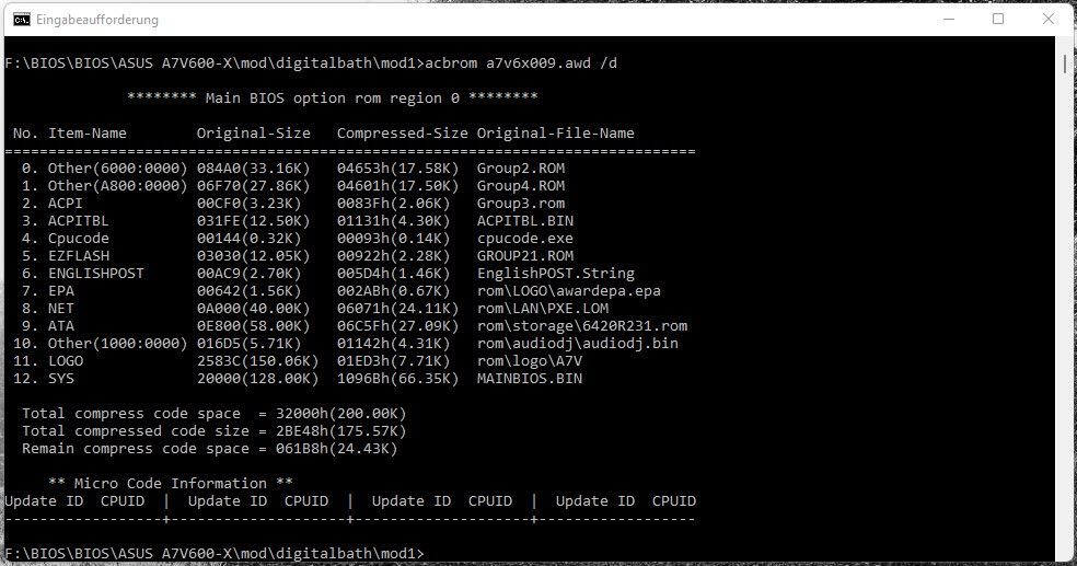
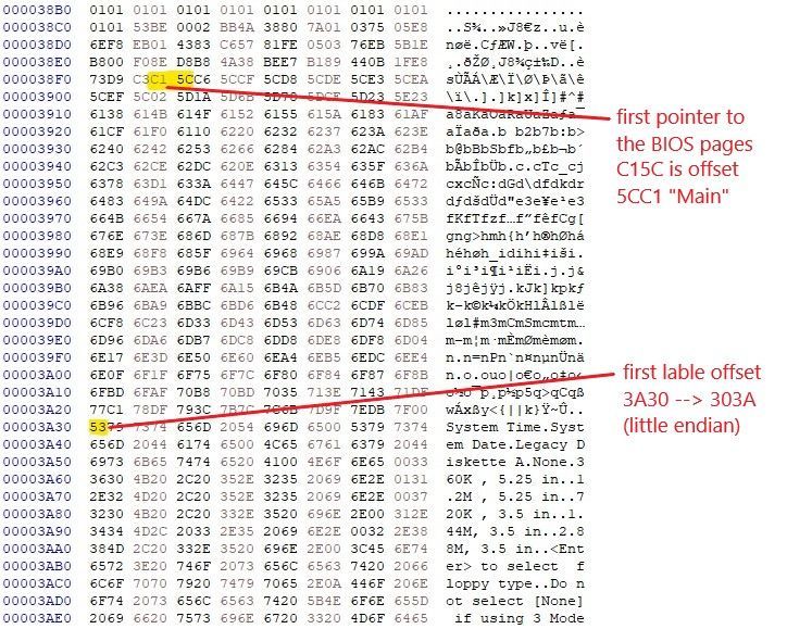
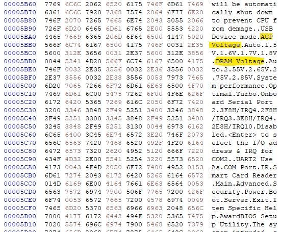
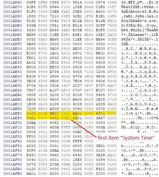
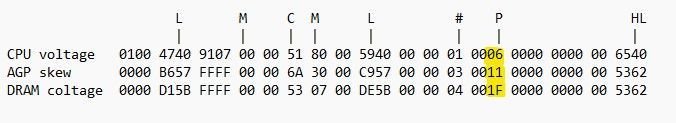
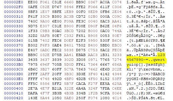
I want to write down some lines about my experience with the mod BIOS for the ASUS A7V600-X board. But what makes the BIOS of this board special? Well, the postscreen says: "AWARD Medallion BIOS 6.0". By trying to look at BIOS modules and items with the tools: awbedit, cbrom and modbin, all three tools refuses to work with this BIOS. After some help from Antinomy and Tzk, we figured out, that we need a special cbrom version for this BIOS called "ACBROM" (A for ASUS?). ACBROM recognizes this BIOS and this is how the modules look like: What I see is, that all usuall modules in Award BIOSes are missing here (_EN_CODE, awardext, awardeyt ...). We also get new modules here like ENGLISHPOST, Other (1000:000), Group2+3+4. After some research, I found the lables to the BIOS items in the Group2.rom module. It seems like the "_EN_CODE" module for the labes is working here in a different way then in the usual Award BIOSes. The Group2 module beginns with a lot of CODE and about a half, the part of the labes begins: We see some pointers to the BIOS pages : "Main", "Advanced", "Security", "Power", "Boot", "Server" and "Exit". I didn't check all pointers below the main menu, but these pointers seem not to contain all lables, just for some. These lables got my attention: Since the BIOS does not have any items for Dram Voltade or AGP Voltage, there should be some hidden items in the BIOS. I should take a look at the items. The BIOS items are still located in the System module "MAINBIOS.BIN". I marked the first item. You see the lable "303A"? It seems like the first lable in the Group2 module is for the first item in the system module. All items are grouped together as a single block of items. They weren't grouped in pages as Tzk found out in his post. Most items begins with a 00 or 01, so they should be all visible, but they aren't. Is there a lookup table with visible and non visible status? I could find anything. I also couldn't find any "$ml$" marker for BIOS pages as normal Award BIOSes do. No wonder the usual Award tools weren't able to read this BIOS. The whole "BIOS structure" is different. I looked for the missing items for Dram- and AGP Voltage and found them in offset 1C4A7h and 1C48Eh. For my first mod, i tried to replace two visible items with the items for Vdimm and Vagp. It didn't help, since they were still invisible. My second try was just to set a different Position marker in the strings (yellow marking in the screenshot above). I uses same position marker as the Vcore item (06 vs 1F) That worked! The non visible items became visible! Now we are able to change the Dram Voltage in BIOS. The bad thing is, these Voltage changes doesn't work. So, these items are useless / non working. My conclusion to this BIOS is, that there are invisible items and they weren't placed in the BIOS menu. By changing the position marker we are able to make this items visible. I will try to make more items visible and test them, but they aren't as important as Vdimm.
-
Many thanks! Well, I am not able to compete to your wprime results. I need more time to improve my wprime efficiency.
-
awesome score!
-
nice one!
-
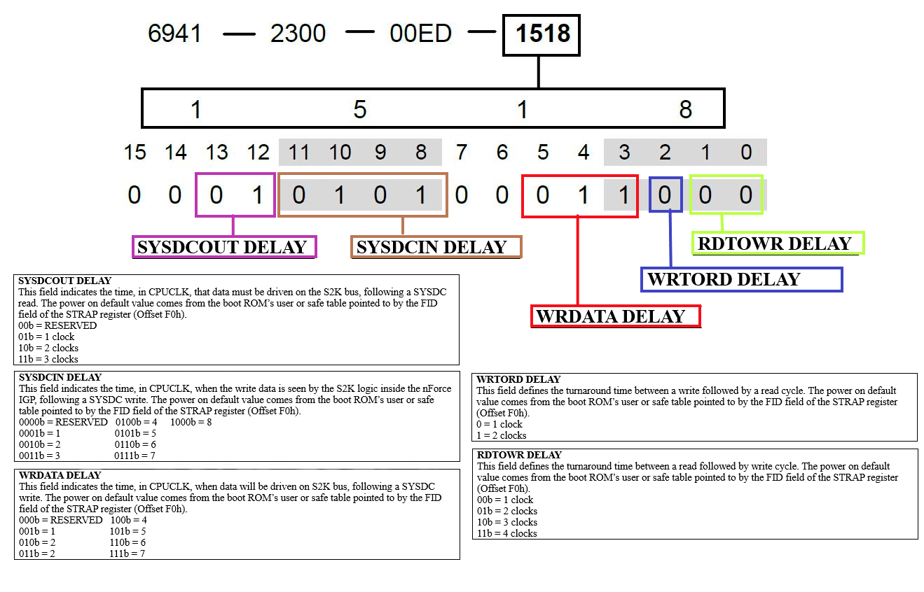
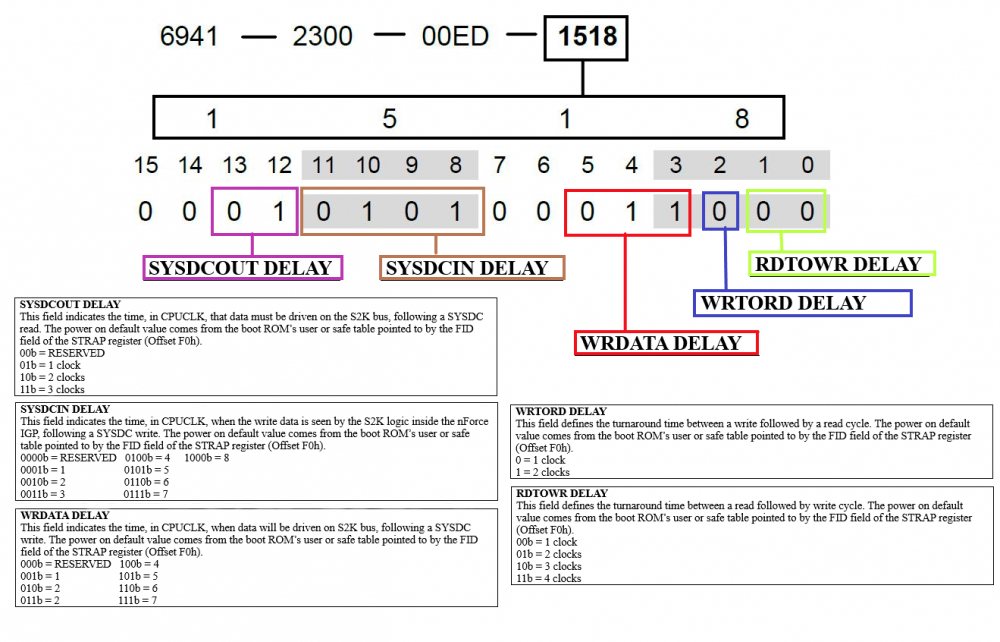
As @Antinomy already in Post #4 discovered, there is a connection between the last two bytes in the romsip multi tables (CPU part) and the S2K PCI register. With the help of the nForce2XT tweaker I was able to discover the right bit mask: The other 6 Bytes of the romsip multi tables seems not to apear in the PCI register. With this information we now have a better view at the romsips. More tests are required so that we can better understand what these timings do.
-
Awesome!
-
good job!
-
great job!
-
>300MHz, awesome!
-
so close... Awesome result!
-
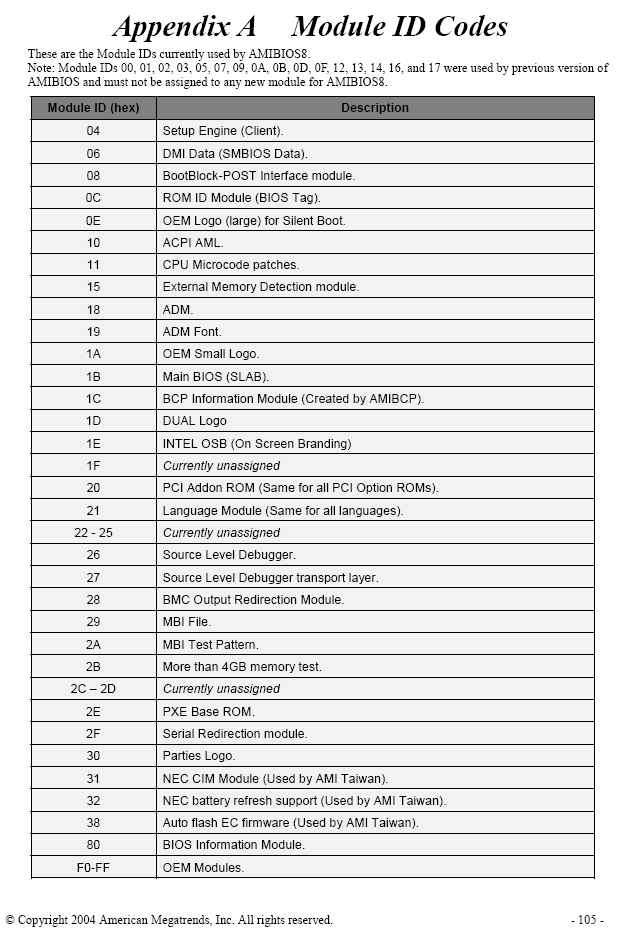
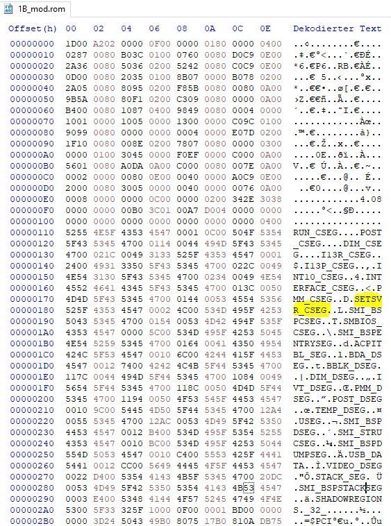
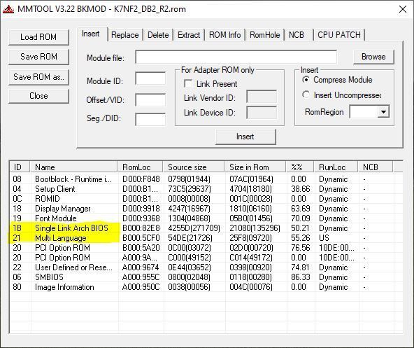
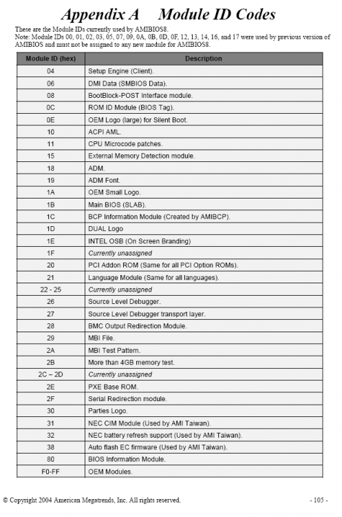
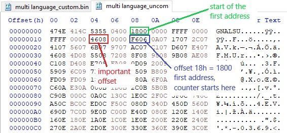
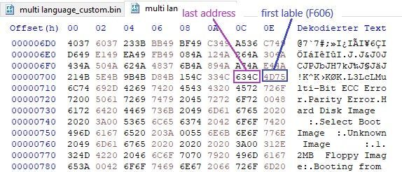
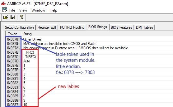
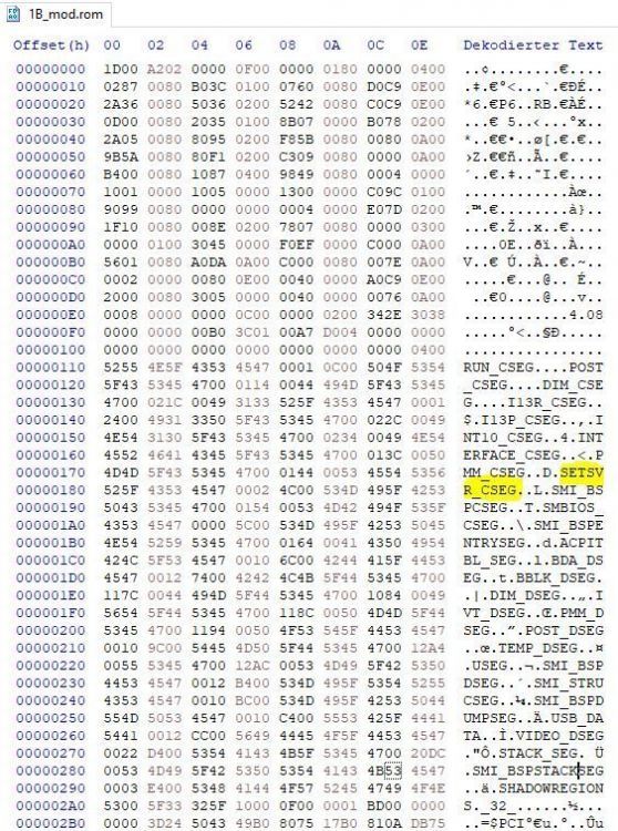
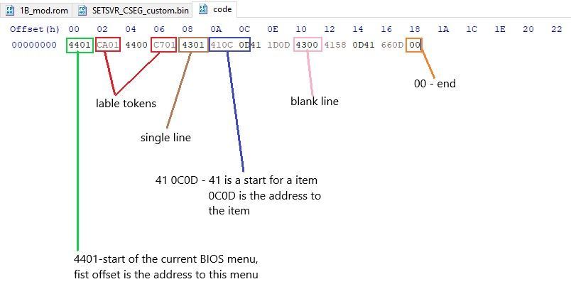
I managed to add BIOS options to a AMI BIOS. My ASRock NF2 BIOS mod now has more DRAM settings. I would like to share a few words about AMI BIOS modding and my main problems I had. 1.0 AMI BIOS AMI BIOS modules are divided into module IDs: The modules we want to mod is 1B (System module) and 21 (language module). 2.0 Language module The first bytes of the language module should be the same as in most AMI BIOSes. Offset 08h and 09h indicate the start of the first address to the lables. This is also the start where the counter begins. Addresses are written down in little endian (offset 06F6 --> F606). Special note to the (red) offset 14h and 15h. This bytes are crucial. Wrong values will cause a crash in AMIBCP. I have no clue what they mean. The last address follows with the first lable F606. No further addresses can be added here. To solve this problem I added 200h free space between the last address and the fist lable. Then I had to correct ALL (!) addresses by +0002 (little endian, +200h offsets). Then I was able to add a lot of new lables! I filled the whole 200h with addresses. Important! I also had to change offset 14h and 15h by +0002! Now, lets have a look at our new lables in AMIBCP: Looks fine now. Lable tokens are important fo find the BIOS strings and menu in the System module. 3.0 Edit System module. The 1b module consists of several parts. The part that I need is called here: SETSVR_CSEG (sometimes other names). You can easily find it with this sequence: There is a tool (ami_1b_utilz) to split the 1B module to its parts. Many thanks here to Antinomy! Now you have to search for the lable tokens. This can help to decrypt the BIOS menu and the BIOS items. Here is some help to find it easier. BIOS items (begins with 01 ….) should look like: (pics from Polygon) BIOS menu code should look something like this: My second problem was to find empy space for my code. There is usable space before the code starts and some space in between. AMI BCP finds this new added code, but the BIOS (after a flash) showed an empty screen with no items. My conclusion is that AMBCP and probably some boards will find this new added code, but my board is not able to use the code from the empty spaces (maybe not addressable area?). To solve this problem, I deleted unimportant and unused BIOS options and moved some code to create empty space for my new option. Well, this worked. My BIOS mod works finally! One sidenote: Moving menus in AMIBCP can cause problems. It seems like AMIBCP moves also the menu in the BIOS code. The BIOS mod now sets correct CMOS values. The next part should be to create a PCI option rom, that changes all BIOS settings in the System part. As far as I know, AMI BIOS is not able to add a ISA option rom. So, exchanging existing LAN boot rom to our modded option rom is the way to go. LAN and LAN Boot has to be enable in BIOS! edit: There are still some points to improve in this BIOS (hidden RAID menu, more settings...). If I find the motivation to do so, I will improve the BIOS mod. ami_1b_utilz.zip K7NF2_DB2_R2.zip K7NF2_DB3_R2.zip K7NF2_DBA_R2.zip
-
Nice! Your work pays off!
-
Rudebwoi - DDR SD-RAM @ 550MHz - 275.2 MHz Memory Frequency
digitalbath replied to Badbwoi's topic in Result Discussions
The 865PE MC should clock even higher. Maybe you have other dimms to try. Something common like hynix BT-D43. -
Rudebwoi - DDR SD-RAM @ 550MHz - 275.2 MHz Memory Frequency
digitalbath replied to Badbwoi's topic in Result Discussions
Nice score for Hynix CTP-D43! -
Well done!
-
nice score with this great board!