Volt modifications
Voltmod and IC database.
Subforums


74 topics in this forum
-
Please use this thread if you need help and/or a new modification. Once a mod is confirmed we will move it to a seperate topic in the specific subforum (GPUs/MBs)
-
- 178 replies
- 37.9k views
- 14 followers
-
-
To keep this subforum as clean as possible we need to follow some simple rules. All pictures have to be hosted here in the forum. Do not use external hosters such as imgur or imageshack Use this thread for vMod requests and general discussions. If you have a confirmed mod post it here. A moderator will check and move the topic to the specific subforum. Use a propper thread title. E.g.: GTX 275 (reference PCB) or ASUS GTX 780 DC2OC (non reference PCB) Please post a high resolution picture of the card (front and backside) at the top of the thread.
-
- 0 replies
- 4.8k views
- 1 follower
-
-
Hey folks, Not sure if there are anyone old enough here left to remember those days with Socket P/479 an Merom CPUs, but here's the deal: I have old obscure motherboard based off GM965 chipset, with Core T7500 CPU in it. All works fine, but I want more magic pixies, so I got myself X9100 CPU. However X9100 is FSB1066 processor, so I'd need to trick it into 800MHz to work, I'd assume. I don't have CPU yet, but pretty sure it will not work directly w/o mods. Anybody have infos/guides left on dusty harddrive somewhere, covering BSEL/VID mods?
-
-
- 10 replies
- 7.7k views
-
-
If you are into xoc and hardmods you might be interested in some of the projects in this post. I made a couple of KiCAD projects in the past and didn't like that they were only available to a couple of people or even got left behind altogether. That's why I created this post to make some of these projects available to the public, for personal use and to be modded for all kinds of hardware. It'll take me a couple of weeks to get everything up here so stay tuned. Here is a quick guide on how to order the pcbs: upload the .zip named "xxx - production files" to JLCPCB (or any other fab of your liking) change the manufacturing settings to what is specified…
-
- 0 replies
- 1.1k views
-
-
I've been messing with this controller for a while now and have some basic voltage control for it. Full range voltage control and other details should be done by the end of the summer. The monitoring should be able to be applied to a 8266 as well. Most of this is based on the xml files detailing the i2c/pmbus interface in the evc2 software + disassembling/decompiling the raspberry pi voltage control software for the epower classified. I also verified this working with a arduino through a level shifter on a 680 classified through the evbot header. Since the epower classified has the controller at address 0x40 instead of 0x46 I modded the binary with a hex editor use t…
-
- 0 replies
- 821 views
-
-
finally got my first powercard working, cut from a 560 ti with a dead core/memory memory vrm is still shorted to ground but the controller is reciving power so there might not be any more work to get it working if the short didn't exist the vrm doesn't require 3.3v and runs off of 12v for power +12v for controller is from pcie so you have to connect one of the 6 pins to the power plane on the front (all the way at the bottom) +5v is needed to enable the controller simple feeback mod for voltage control and an led for +12v power indication unfortunately there is little ground but since vmem is shorted to ground all of vmem works as a ground p…
-
- 0 replies
- 697 views
- 1 follower
-
-
I EPowered a reference Radeon HD 5870 and have been running into problems getting it to work. The OS I'm booting into has the correct video drivers as I installed them prior to the mod. Initially I wasn't able to get any picture but the system would boot up fine (as I could tell via boot codes, drive activity, and leds on my mouse n such). Then I looked up the memory's voltage and used 1.5V for that and I initially got picture, but it blackscreened whenever I got into the OS. I could sometimes see flashes of picture if I jostled the card around a bit but could never figure out if it's my mount or my PCI Riser cable. Right after rebooting a few times my system we…
-
- 1 reply
- 933 views
-
-
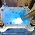
Elmor recently started taking orders for the AMPLE 20A power card. It’s a simple little single-phase VRM that can be used to replace a broken VRM or simply overcome that pesky OCP/OVP. The most common potential usage would be for a GPU memory rail. However, with an output voltage from 1.0-3.4 V it could be used for many different applications. I obtained a test sample of this new device and I intend to put it to the ultimate test. I have an RX 580 GPU with a damaged memory voltage rail, but otherwise the GPU is in perfect condition. The plan is to solder on the AMPLE power card and observe the impact on the memory overclocking. I know what the card was capable of be…
-
-
- 11 replies
- 2.6k views
-
-
Hey guys, this card worked for about 3 years as a daily driver (wasn't OCed) when it started to crash the PC. It would just shut off instantly, like when it's a PSU issue. The PSU was fine though. I replaced the card and the problem went away. I finally got around to repairing the card and traced the problem down to one of the Mosfets. The card powered up when I would leave the 8-pin out - the 8-pin powers the lower 4 GPU Mosfets - and sure enough, one of them was fried (no resistance between two of the pads). The card powers up fine with the 8-pin in now, although the lower 4 Mosfets are still out. First question: What kind of manufact…
-
- 1 reply
- 1.8k views
- 1 follower
-
-
Hey guys, got an asus gtx 580 dirrectCUII that i have volt modded but the issue i thinking im having is that i may be tripping OCP on the card as at about 1.33 volts the whole system just shuts off when i get into firestrike. Does anyone know how i can disable ocp on this card if it has it? i cant find any datasheets on the VC its a "SHE ASP0907", the only way i was able to mod it was due to someone else posting a picture of their solder work on another forum where they used it as an external VRM. Yes i will cover those wires with some hot snot at a later date. Any help will be greatly appreciated. Cheers ShmoeMo
-
-
- 24 replies
- 3.2k views
- 2 followers
-
-
Posted by Pepinorang on his Facebook, credit goes to Vivi. This fixes blackscreen bug benching and improves the ocability.
-
-
- 18 replies
- 8.2k views
- 3 followers
-
-
Hey guys. A little bit ago now i cut the vrm of a DCUII 780 and verified it had no shorts and since then i have been unable to get it to power up. I have supplied the chip with 3.3 volts for VCC, EN, and PSI yet i cannot get it to output properly. It will output 3 oddvolts on the main vrm (which aint right) but has no current capability. An 8 ohm load will drop it to basically nothing. The main VC is an ASP 1212, linked below. Is there a sense line or another enable line somewhere i need to hit with 3.3 volts? I have attached a picture of what i have so far. https://www.infineon.com/dgdl/pb-asp1212.pdf?fileId=5546d462533600a40153567f4b2128a4
-
- 2 replies
- 1.5k views
-
-
Hi there! I was directed to this subforum to post a survey for interest on a volt mod pcb a friend and I created. The files for the board are open source and on my github page. If anyone wants them, just let me know and If allowed, I will post the link to them. https://forms.gle/SsqLTnhwMYSPTzk48 This survey is just to gauge interest in this product to see if you all would like to own one. The email collection is to inform those who take this survey of when they go into production and other news related to the vmod board. It will not be used for any other reasons nor be given out to anyone. In the survey before the render of the board, there i…
-
-
- 6 replies
- 2.2k views
-
-
Hey guys. Recently cut the vrm off a dead asus 780 and now am wanting to get it ready to put on a 750 ti. Problem i am facing after hooking up the enable pin to 3.3v is that the vrm is outputting 1.4 odd volts BUT it cant supply any current. Just putting a simple 8ohm speaker across the output makes it drop to 200mv. The controller is an ASP1212 (Link below) Is there something i have missed when enabling the controller? https://www.infineon.com/dgdl/pb-asp1212.pdf?fileId=5546d462533600a40153567f4b2128a4
-
-
- 7 replies
- 1.7k views
- 1 follower
-
-

hello, powerboard dual output with gtx 780TI matrix The Matrix tool work ? Cut of the printed circuit and solder LN2 mod GPU: ASP1212 datasheet: http://www.irf.com/product-info/datasheets/data/pb-asp1212.pdf ONLY 3.3v MEM: Up1631p and IROG Black: 3.3V Red: 5V Vmod: OVG: 10K OVM: 50K enjoy
-
- 2 replies
- 2.5k views
- 1 follower
-
-
1. They make trimmer adjustment/tuning tools. 2. They make trimmers that are specifically for panel mounting. 3. You can get panel mounting retrofit kits for standard trimmers too. I wish somebody'd told me about these things. Because I use them all the time now. The adjustment tool is the coolest thing since sliced bread. And panel mounting trimmers is just about as cool(if you've got volt mods on components inside a case anyway). Drill hole > mount trimer > adjust trimmer without having to open your case(and/or without having to reach inside your opened case). GENIUS! ?
-
-
- 5 replies
- 1.9k views
- 1 follower
-
-
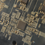
hi all , today i made dual output powercard from a dead gtx580 DC2 , but with functional VRM. on GPU VRM we have 8 power phase and 32 mosfet transistors NXP 7030AL ( N-channel TrenchMOS logic level FET) witch can go up to 50A at 80-100 degree , pwm used are ASP0907( remarked) , output filter has 10x 820uF solid cap rated 3V , 4x470uF POS cap and 20x MLLC DDR VRM we have 2 phase and use as pwm uPI6205A and 8x NXP 2530AL up to 25A , output filter 4 x820uF solid cap and on back side the yellow tantalium cap! - cutt the PCB and make sure that are NO short in pcb layer!! - add +5v ( home made DC-DC converter with L7805 - TO220 package) - add +3.3v ( i use a AMS11…
-
-
- 25 replies
- 14.5k views
- 4 followers
-
-
Some Background: Even though I have had an EPOWER V for quite a while I found myself using the older EPOWER classified instead. Having Software voltage Control is a must have feature for me since I find the buttons very awkward to use when the EPOWER is mounted on a GPU. When the EPOWER V was released voltage Control over USB-C was promised, but since that still doesn’t exist, I started poking to try and see if I could build a solution myself. To my surprise I found that there is voltage control already implemented. I have no idea why this is hidden, and it doesn’t work over USB, but it does solve my problem of reaching around my card to try and change vol…
-
- 1 reply
- 2k views
- 2 followers
-
-
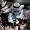
Hello all Every now and again, I end up with a few things that I can't fix. This is one of those times. These aren't benching cards, just things that pass through my hands. Any ideas or help would be appreciated 1/ Asus GTX570 DCUII vCore = 0 vGDDR = 0.51v No signs of damage. Fuses have been replaced. 12V inputs are fine. FB, OCP, 3.3v and vCC input values for both vCore and vGDDR are as expected, so no obviously damaged components there. Both controllers and their surrounding areas have had a pass from a Hot Air Station in case of dried-out solder joints. 2/ Asus GTX580 DCUII vCore = 0 Same as above. 3/ MS…
-
- 2 replies
- 1.5k views
- 2 followers
-
-
I just bought a GTX 780 classified that was supposedly broken on ebay. I paid $60 and I planned on using it for a homemade epower. Seller stated PLL light was out which means that PLL vrm isn't functioning. PLL is a rather low volt and current vrm most cards are 1-1.25v at less than 5a. I figured I would try to put a little ebay 3a dc-dc buck converter I had for other zombie projects to power the PLL. If that failed then I would cut it in half and have an epower. When I got the card I noticed 3 missing smd caps and one resistor. I figured the caps didn't really matter but checked on Techpowerup hi-res picture for resistor size. It happened to be 0 ohm. I just used a small…
-
- 1 reply
- 1.9k views
-
-
This one was easier than I thought a few people said it was hard and won't publicly share there work. I will though. All I did was look at the pinout of the chl8266 controller. The three 3.3v vcc pins 36, 28, and 3 are all connected to the same 3.3v plane. When power is added to the 3.3v power plane it powers all the pins needed. I just picked pin 36 traced to its capacitor and solder to it. The EN pin is 11 and this is where it got tricky because it goes strait to a via and buried trace. The cool thing about the 480&580 ref PCB there is a second controller pad that is not populated but all traces are there and hooked up. I just check continuity between pin 11 on the…
-
-
- 9 replies
- 4.1k views
- 1 follower
-
-
Sorry for my English. Full document in pdf format in Russian and a little English here. Vmem mod part 1. 20 or 50 kOm VR solder between 6 and 4 pins, LM358 operational amplifier. To chenge the voltage from 2.85v to 3.2v. Before you do, measure the resistance between the pin. After solder a resistor trimmers, put the value close to what it was before all the action and only then turn on .reducing the resistance you increase the voltage. Vmem mod part 2. Change the memory power from the 3.3 volt on the 5 volt supply for the memory chips are Winbond BH5 and others. The control of the increase o…
-
- 1 reply
- 2.8k views
-
-
Hello everyone, I'm new as a member here, yet I was looking for advice here for more than 10 years now. I felt the need to join and start a new thread because I need help, if there could be any. I attempted the notorious 0.95v rail mod on my R9 290, which seemed to work ok, initially. The PC booted successfully, got into Windows, played a little Doom 4, run furmark for a while, then attempted to overclock. In MSI Afterburner Maximized AUX voltage and Memory clock and raised the voltage to +200mv, raised the core to the point furmark froze. Then I tried adjusting the variable resistor which I soldered before. The rail measure was showing 0.94v to that point. After so…
-
VRMtool 0.04 (2016-07-17) To simplify poking around in I2C registers I wrote a simple tool to dump and modify the I2C registers of VRM controllers connected to AMD/ATI cards. This now evolved into a handy tool to control many aspects of supported VRM chips. Currently I only have the RX 480 reference card to test and as such only for the IR3567B the tool is able to interpret and change some of the PMBus commands and I2C registers. Additional information about registers of this and other voltage controller chips are very welcome. Special thanks go to elmor for helping with the IR3567B PMBus commands. The tool makes intense use of the I2C bus while it is runnin…
-
- 28 replies
- 16.5k views
- 2 followers
-
-
So this gave me a bit of an undue headache because of a bad joint to ground, and I was wondering why nothing was working Runs an RT8867A, data sheet attached. Pull one of the purple points to ground (pin 6) with a 20k - 40k ohm pot. Do I even need to do the shunt mods? A quick run proved easy points on a $25 card running stock cooling, should be good under LN2 But I got beaten by 4ms if only I knew how to tweak gpu pi....
-
- 1 reply
- 2.9k views
- 1 follower
-


.thumb.jpg.5907ecd80a822620422128b880b1b4e8.jpg)